United states posted 31 dec 2017. Wiring 1214c dcdcdc cpu started by allen82686 31 dec 2017.
Digital Io Connection To S7 1214c Entries Forum
1214c dc dc dc wiring diagram. See appendix c spare. Allen82686 0 hi i am new. Wiring 1214c dcdcdc cpu sign in to follow this. Cpu 1212c wiring diagrams table 1 cpu 1212c acdcrelay 6es7 212 1be31 0xb0 ① 24 vdc sensor power out for additional noise immunity connect m to. 10 do relay 2 a. I am currently finishing my as.
14 di 24 v dc. Cpu 1214c wiring diagrams table 1 cpu 1214c acdcrelay 6es7 214 1bg31 0xb0 ① 24 vdc sensor power out for additional noise immunity connect m to chassis ground even if not using sensor supply. 1 ma input delay for rated value of input voltage. ② for sinking inputs connect to m shown. Rated value dc 24 v for signal 0 5 v dc at 1 ma for signal 1 15 vdc at ma input current for signal 1 typ. Dc 204 288v dc programdata memory 100 kb.
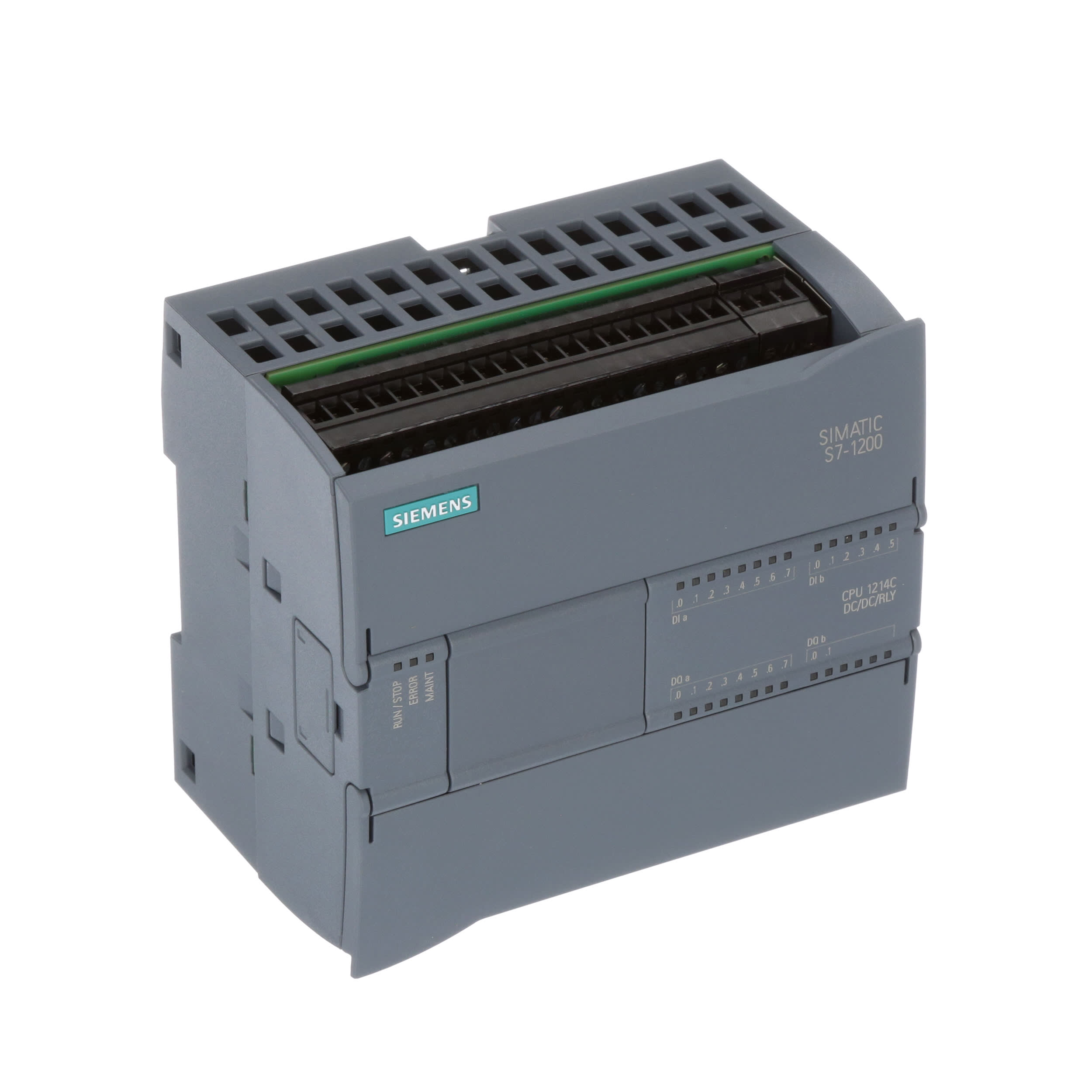
6es7214 1hg40 0xb0 cpu 1214c dcdcrelay 14di10do2ai simatic s7 1200 cpu 1214c compact cpu dcdcrelay onboard io. 1is it npn or pnp. Dc 204 288v dc programdata memory 100 kb. Siemens industry online support. For sourcing inputs connect to m. The supply voltage is 204 288 v dc.
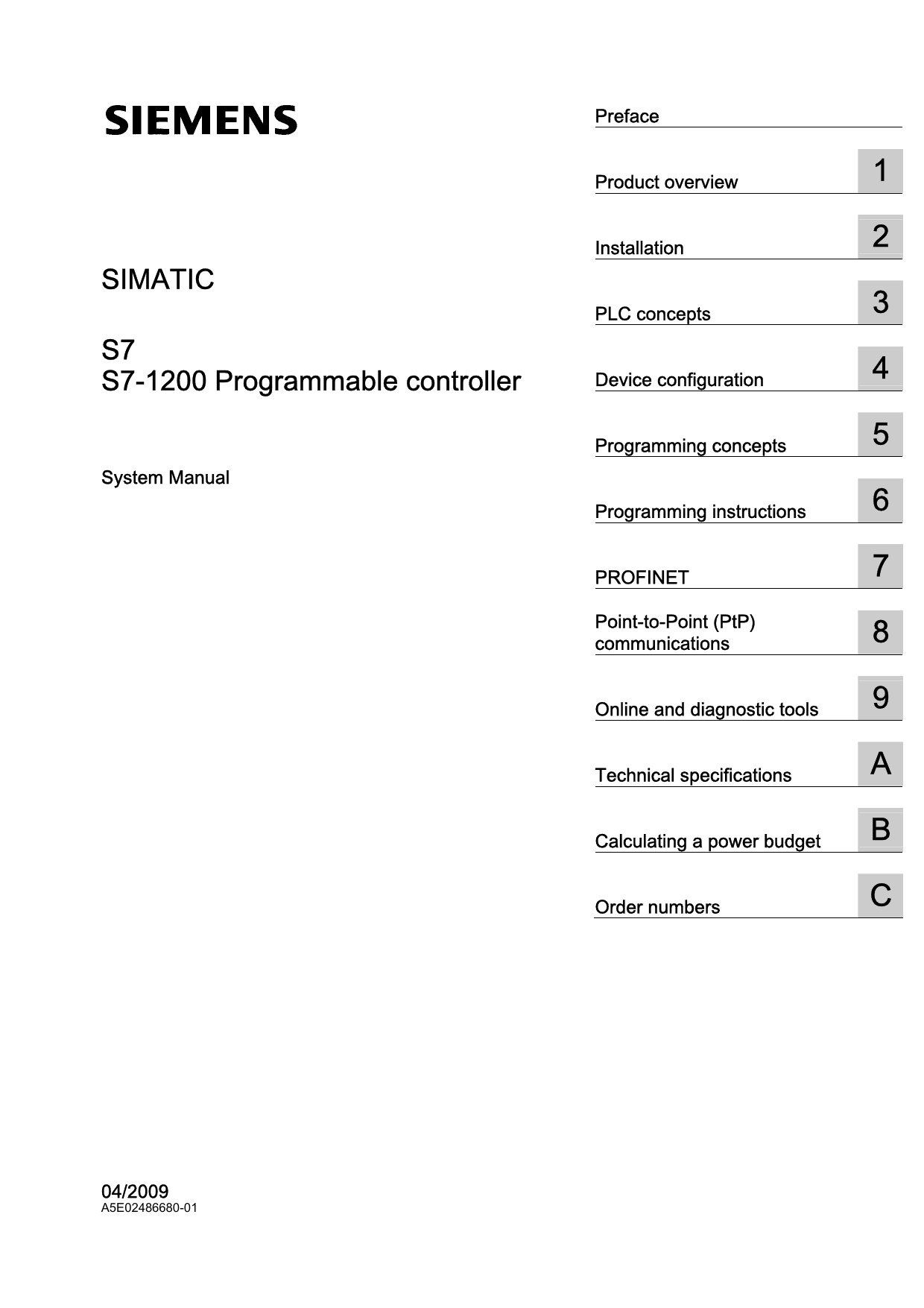
6es7214 1hg40 0xb0 cpu 1214c dcdcrelay 14di10do2ai simatic s7 1200 cpu 1214c compact cpu dcdcrelay onboard io. I couldnt find any data so unable to connect the drive with plc. 2 ai 0 10 v dc power supply. Wiring diagrams for siemens nema contactors and starters. 2 ai 0 10 v dc power supply. Simatic s7 s programmable controller.
Actually i am working on positioning of a servo drive estun edb 15ama with 1214c cpui want to know about the inner diagram of of digital outputs of cpu 1214c dcdcdc 6es7214 1ae30 0xb0. One profinet port is provided for communication and programming. X11 connectors must be gold. 4 posts in this topic. 10 do relay 2 a. The simatic s7 1200 compact cpu 1214c dcdcdc 6es7214 1ag40 0xb0 from siemens has 14 digital inputs 10 digital outputs and 2 analogue inputs.
Cpu c wiring diagrams cpu c wiring diagrams table 1 cpu c acdcrelay 6es7 bgxb01. 500w push pull dc to dc converter circuit diagram using uc3642 figure below shows a 500w push pull dc to dc converter circuit diagram using uc3642 uc3706 and uc3901 ics. 14 di 24 v dc.
Gallery of 1214c Dc Dc Dc Wiring Diagram