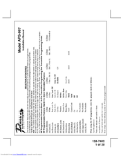
Prestige aps997z vss 1 mile range 2 way vehicle specific ready remote starter kit. Arming the system active.

Top 8 Car Alarms Of 2020 Video Review
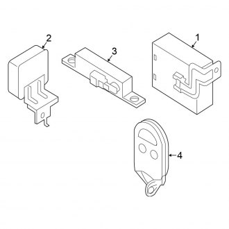
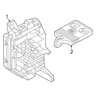
Aps997z wiring diagram. Assumed timed crank option 2 10 setting 4 assumed time crank is the last feature of option 2 10 for remote starting. Refer to start kill diagram on page 29. Refer to start kill diagram on page 29. Operating the prestige aps997 remote start system. The power wire registers 12 volt at all times. The operation of the security and convenience system as described in this manual is applicable to most vehicles.
Process complete no further programming required. If you need more information on the all wiring functions and necessity on all the wiring on your audiovox pursuit or prestige alarm remote start system this video will cover it. Click or call toll free 1 866 244 8004. The power wire registers 12 volt at all times. Before making this connection remove all module fuses until the system is completely connected. Page 16 channel 3 relay wiring detail green w black trace wire.
300ma latched channel 4 output the green w black trace wire supplies a 300 ma switched output whenever channel four of. Press and release the arm button on the key chain transmitter one time. 1 owners guide for models. 2019 o lectronics corporation. Pressing the pre programmed transmitter buttons will access channel four and will remain active for up to 20 seconds as long as the. Before making this connection remove all module fuses until the system is completely connected.
Red 12 volt input the red wire connects to the vehicles primary 12 volt wire to power the system. This is intended for vehicles with built in anti grind feature or that do not have a 12v positive. However due to the configuration of some vehicles some functions andor. Red 12 volt input the red wire connects to the vehicles primary 12 volt wire to power the system. Turn off the ignition exit the vehicle and close all doors hood lid and trunk lid. The stator wire should now test between 12 14v dc at idle.
300ma latched channel 4 output the green w black trace wire supplies a 300 ma switched output whenever channel four of the receiver is accessed. This wire will be routed to the vehicle ecm tach input or through the firewall into the engine compartment and connect to the negative side of the ignition coil. Page 16 channel 3 relay wiring detail green w black trace wire.
Gallery of Aps997z Wiring Diagram