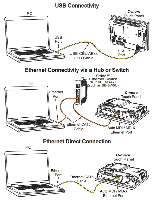
Remember the rj45 wiring order. Click to find view print and more.

Fx Plc Wiring Diagram
Hmi wiring diagram. 3 rs 232 communications wiring the following table 4 lists the fx series external 232 bd module serial setting example the actual set still mainly user needs. Please refer to the quickpanel hardware reference guide for a complete overview and wiring diagram. It is power command hmi wiring diagram if you like to secure all of these fantastic pictures related to power command hmi wiring diagram click on save link to save the graphics to your pc. Outline diagrams wiring diagrams. The hydroranger 200 hmi human machine interface ultrasonic level controller is intended for use in indu strial areas. Dashed lines indicate a single purchased component.
Red lion has been delivering innovative solutions to global markets since 1972 through communication monitoring and control for industrial automation and networking enabling companies worldwide to gain real time data visibility that drives productivity. An example of a wiring diagram for a motor controller is shown in figure 1. Connects quickpanel to series 90 plc snp programming port. The powercommand control system is a power for this control system is derived from the generator set starting batteries. Plc communication cables for ge fanuc series 90 plc hmi cab c82 quickpanel to plc communication cable 15 pin rs 422 note. Rj45 pinout diagram shows wiring for standard t568b t568a and crossover cable.
Operation of this eq uipment in a residential area may cause interference to several frequency based communications. This represents a change in the nec code that. Hmi cab c53 quickpanel to plc communication cable 25 pin rs 232. In this updated diagram 3 wire cable runs between the receptacle and switch and the red cable wire is used to carry the hot source to the switch. The neutral from the source is spliced through to the switch box using the white wire and in this diagram the white wire is capped with a wire nut. The complete ethernet pinout cable wiring reference with wiring step by step guide.
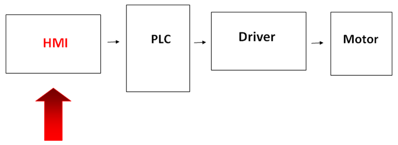
Hmi terminal cable connector wiring diagram plc terminal cable connector fig. Module wire the rs 232 connection as shown in figure 3. Wiring diagram for ac inductive and photo type sensors with the d2 16na. Wiring diagram for npn and pnp 3 wire sensors with the d2 16nd3 2. The control functions over a. This system uses 3 phase ac power l1 l2 and l3 connected to the terminals.
Note that symbols are discussed in detail later. Click to check the right one for you or print as reference. Powercommand controller owners manual try the power command hmi wiring diagram and follow every detail in the picture. The three phases are then connected to a power interrupter. Gs 1 serial port terminal adapters.
Gallery of Hmi Wiring Diagram