Chris craft 264112 views. Increased btuh load high product tem perature coil icing product frosting and external sweating.

4490c8 Kw T800 Fan Wiring Diagram Wiring Library
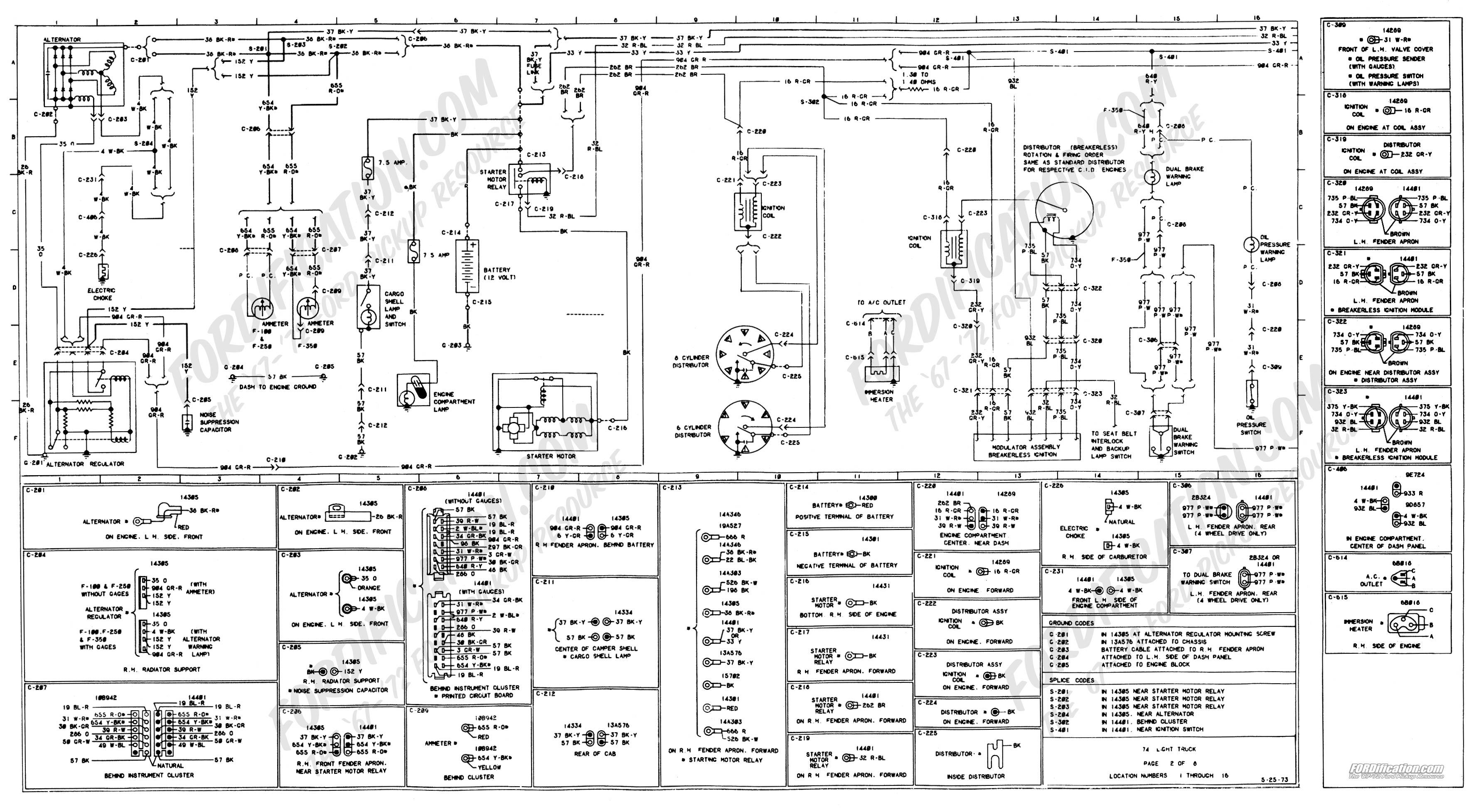
Kysor warren wiring diagram. See wiring diagram for layout. Grasslin dtsz defrost timer with typical wiring diagrams installation and operation manual. Original beacon installation and operation manual part 25001501. Finally found a wiring diagram and saw that there is a safety for the anti sweat heaters. Kysor warren whose srolflvrqhrifrqwlqxrxvlpsuryhphqw uhvhuyhvwkhuljkwwrfkdqjhdwdqwlphvshflàfdwlrqv designs or prices without incurring obligation. It is imperative that the pins of the bulbs and the shelf power cords be.
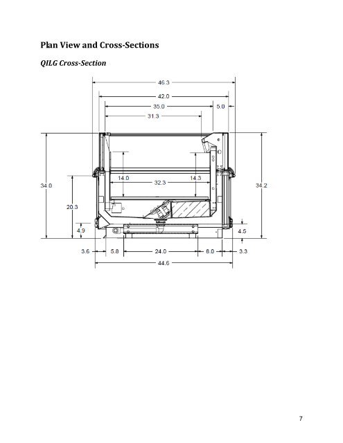
Heatcraft worldwide refrigeration is a business segment of lennox international inc a leading global provider of climate control solutions. Install the dashboard cover and tighten the screws securely. Increased btuh load high prod. They have 2 sections tied together. Doe 2017 compliant. 262006 2 addendum ballast relocation 2.
Failure to properly install electrical wiring and control wiring as per wiring diagrams defrost settings and. 24 connect the 15 pin wiring connector. Failure to properly install electrical wiring and control wiring as per wiring diagrams defrost settings and temperature set points may result in operational issues such as the following. I just looked on the kysor warren website and they show nothing other than a wiring diagram on it. Kysorwarren special hook a pack systems are used or 18 and 20 shelves are used above. Contact your kysor warren service.
Here is a quick guide to understanding a kysor warren wiring diagram. Chandler kysorwarren and interlink. How to wire a doorbell diy live demo and wiring diagram duration. If you want to find the other picture or article about kysor warren wiring diagram rack wiring. Then install the trim piece. Kysor warning and engine shutdown system 5402 control module replacement business class trucks service manual supplement 0 june 1991 1001.
One section the anti sweat heaters work and the other section does not. Canopy ballast location raceway ballast location 1. Failure to properly install electrical wiring and control wiring as per wiring diagrams defrost settings and temperature set points may result in operational issues such as the following. Problem is we cant find the switch. 262006 3 addendum ballast relocation warning. Wiring diagram index name description page aa power distribution frc 3 ab power distribution frc 4 ac power supply circuit protection 34 ef 5 ad power supply circuit protection 44 ef 6 ae grounding 7 af starting and charging 8.
Gallery of Kysor Warren Wiring Diagram