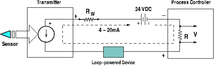
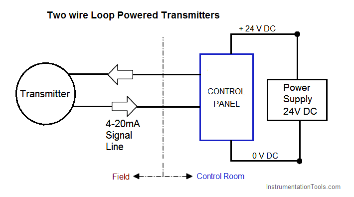
In a 4 20ma current loop all the signalling current flows through all devices. Benefits can include reduction in engineering costs.
Instrumentation Loop Diagrams Instrumentationtools
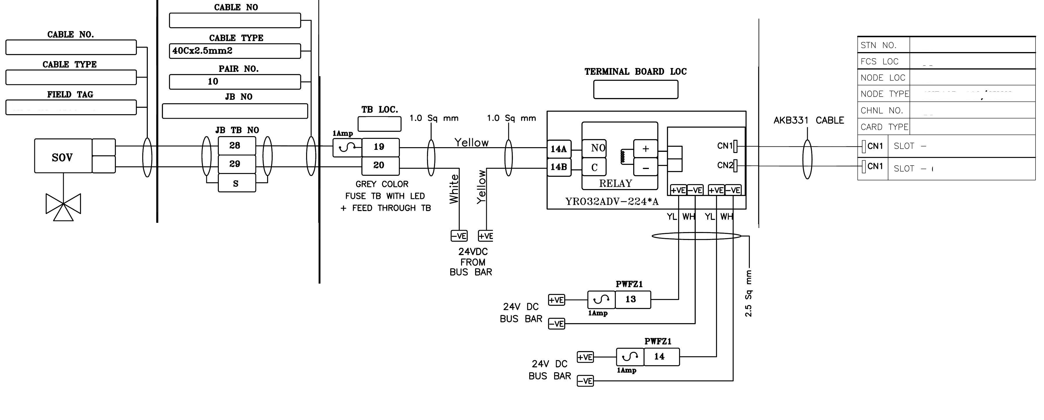
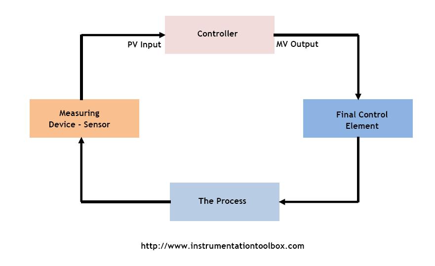
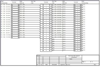
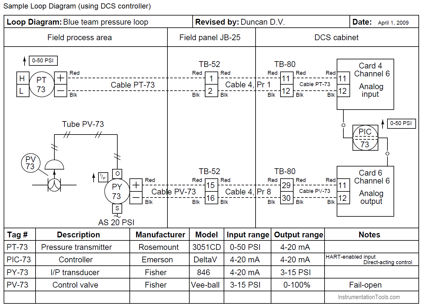
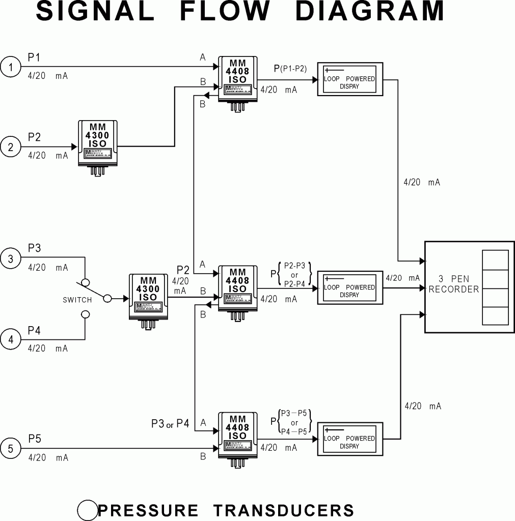
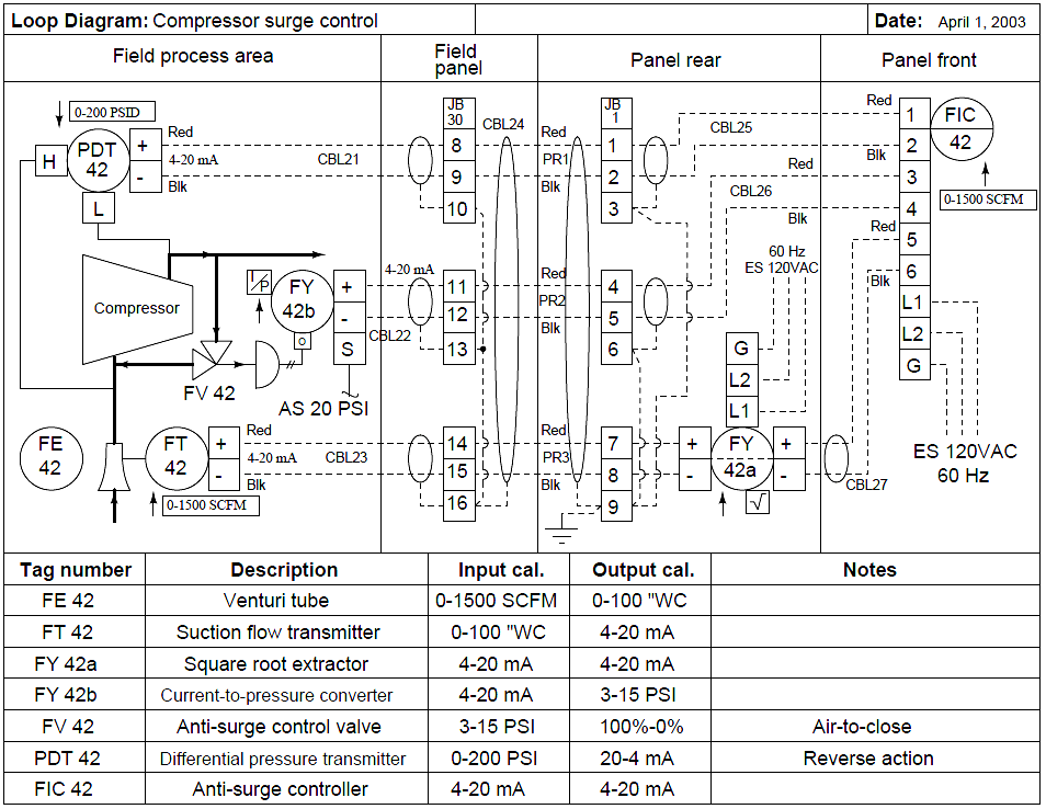
Loop wiring diagram instrumentation. Loop diagrams are fairly constrained in their layout as per the isa 51 standard. The 4 20ma current loop is a very robust and popular sensor signalling standard. Loop diagrams are fairly constrained in their layout as per the isa 51 standard. One is the field side and other is control room side. Basics of instrument loop diagrams they show all the instruments in a control loop each instrument bubble in a loop diagram represent an individual device with its own terminals for connecting wires. Dashed lines in instrument drawings represent individual copper wires rather than whole cables.
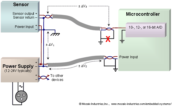
And instrument tag ending with terminal numbers. The process is illustrated in sections or subsystems of the process called loops. Instrument loop diagrams are suitable for general use throughout industry. Current loops are ideal for data transmission because of their inherent insensitivity to electrical noise. When a loop diagram shows you exactly what wire color to expect at exactly what point in an instrumentation system and exactly what terminal that wire should connect to it becomes much easier to proceed with any troubleshooting calibration or upgrade task. When a loop diagram shows you exactly what wire color to expect at exactly what point in an instrumentation system and exactly what terminal that wire should connect to it becomes much easier to proceed with any troubleshooting calibration or upgrade task.
Pids and loop diagrams are construction and documentation drawings that depict the flow of the process and illustrate the instrumentation control and measurement interactions wiring and connections to the process. Find the top 15 loop diagram questions here. Instrument loop diagram ild represents a connection from the field instrument to control room. Tag the instrument wire following the instrument tag by adding and on the instrument side. Vice versa instrument loop diagram is divided into two basic sections. It is important to consider their value for design construction checkout start up operation maintenance rearrangement and reconstruction.
Vice versa fieldside is again divided into field area and junction box. Loop diagram helps us to read the wiring connections from field instruments to system cabinet.
Gallery of Loop Wiring Diagram Instrumentation