Close we use cookies in order to optimise this website and for continuous improvement. By using this site you agree to the usage of cookies.

Valve Automation By Automated Valve Amp Control
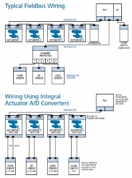
Mov rotork wiring diagram. Rotork valve actuator wiring diagram wiring diagram is a simplified customary pictorial representation of an electrical circuit. Three phase power supply remote control indication and interlocks reversing contactor starter local controls auxilary limit switches motor and. Reduced internal wiring and connections. Rotork is the global market leader in valve automation. It shows the components of the circuit as simplified shapes and the capacity and signal associates in the company of the devices. College of engineering components.
In addition the k range high torque counter switch mechanism can accept both extra end position and mid position switches. It shows the components of the circuit as simplified shapes and the capacity and signal contacts along with the devices. The wiring diagram number identifies the. 0421 e112 motor operated valves course 05 mov controls slides. Rotork mov wiring diagram wiring diagram is a simplified agreeable pictorial representation of an electrical circuit. The same wiring diagram options as the rotork k range product.
Rotork iq3 range actuators remote wiring schematics. Rotork wiring diagram selector. Kevin g dewall created date. Disengage the motor and operate the valve independentlyrotork document search area search for and download documents wiring diagrams and product. For further information please refer to our privacy policyprivacy policy.
Gallery of Mov Rotork Wiring Diagram