Notifier nfs2 3030 wiring diagram wiring diagram is a simplified gratifying pictorial representation of an electrical circuit. The notifier nca 2 is a second generation network control annunciator for the noti fire net or high speed noti fire net networks compatible for use with onyx series nodes such as the nfs2 3030 nfs 3030 nfs 320 nfs 640 and nfs2 640 fire alarm control panels as well as first generation nca network control annunciators.

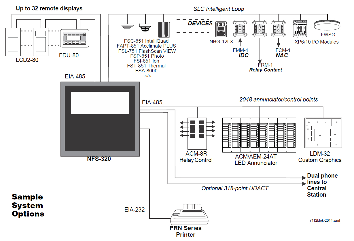
Notifier Intelligent Control Panel Slc Wiring Intelligent
Notifier nfs2 3030 wiring diagram. Fire alarm control panel 68 pages control panel notifier nfs2 3030 operation manual. 2 nfs2 3030e installation manual pn 52544k1 02142012 fire alarm system limitations while a fire alarm system may lower insurance rates it is not a substitute for fire insurance. Nfs2 3030 programming manual pn 52545n1 07182014 3 installation precautions adherence to the following will aid in problem free installation with long term reliability. Warning several different sources of power can be connected to the fire alarm control panel. The nfs2 3030 intelligent fire alarm control panel is part of notifiers ul listed onyx series. An automatic fire alarm systemtypically made up of smoke detectors heat detectors manual pull stations audible.
Warning several different sources of power can be connected to the fire alarm control panel. Control unit and associ. The nfs2 3030 is the complete solution for large scale applications requiring superior performance. 43 nfpa 72 central or remote station fire alarm system protected premises unit the figure below shows typical wiring diagram for a nfpa 72 1999 central station fire alarm system protected premises. The nfs2 3030 supports over 3000 intelligent devices on ten signaling line circuits perfect for protecting large scale applications. Nfs2 3030e installation manual pn 52544n1 07182014 3 installation precautions adherence to the following will aid in problem free installation with long term reliability.
Nfs 3030 installation pn 51330c 10282003. It shows the components of the circuit as simplified shapes and the power and signal contacts amongst the devices. 2 nfs2 640e installation manual pn 52741k1 03062012 fire alarm system limitations while a fire alarm system may lower insurance rates it is not a substitute for fire insurance. Power limited circuits within the backbox with adhesive squares figure 319 typical wiring in a four row backbox nfs2 3030e installation manual pn 52544n1 07182014. Control unit and associ. An automatic fire alarm systemtypically made up of smoke detectors heat detectors manual pull stations audible.
Disconnect all sources of power before servicing. Control panel notifier nfs2 3030e installation manual. Disconnect all sources of power before servicing. If additional knockouts are added to the backbox proper separation of power limited and non power limited separating non power limited and wiring should be maintained.
Gallery of Notifier Nfs2 3030 Wiring Diagram