Usb 30 is the third major version of the universal serial bus usb standard for interfacing computers and electronic devices. The daughter card accessible to an end user from the front of a chassis.
Teardown Revives Hopes That Lightning Might Be Usb 3 0
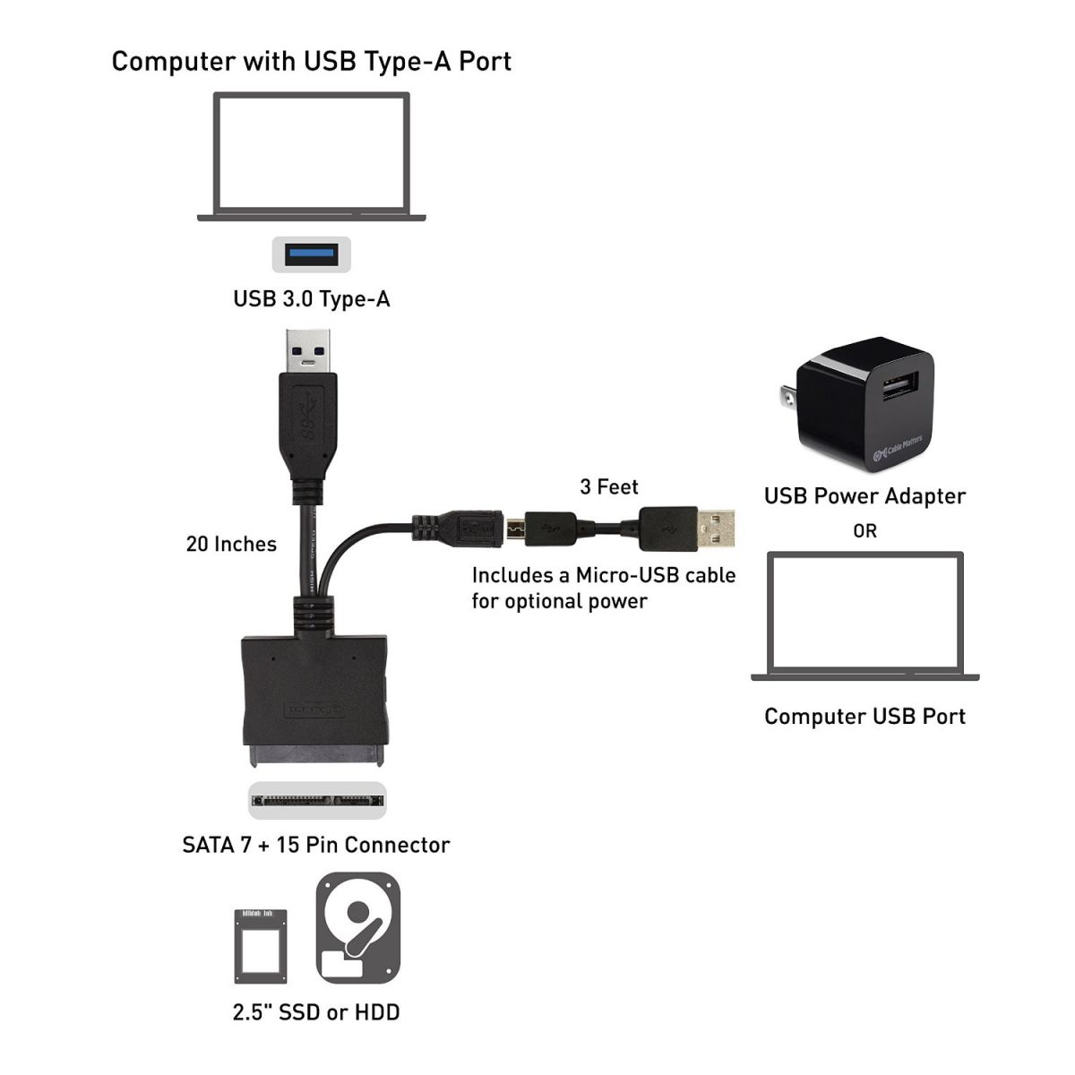
Usb 3 0 wiring diagram. The usb device that uses full speed bandwidth devices must have a twisted pair d and d conductors. Usb a b 20 and 30 cable pinout. Usb 30 to usb 20 front panel adapter for pc installation video duration. It shows the components of the circuit as simplified shapes and the aptitude and signal associates surrounded by the devices. A wiring diagram usually gives information practically the relative turn and promise of devices and terminals upon the devices to incite in building or servicing the device. Usb 30 wiring diagram wiring diagram is a simplified tolerable pictorial representation of an electrical circuit.
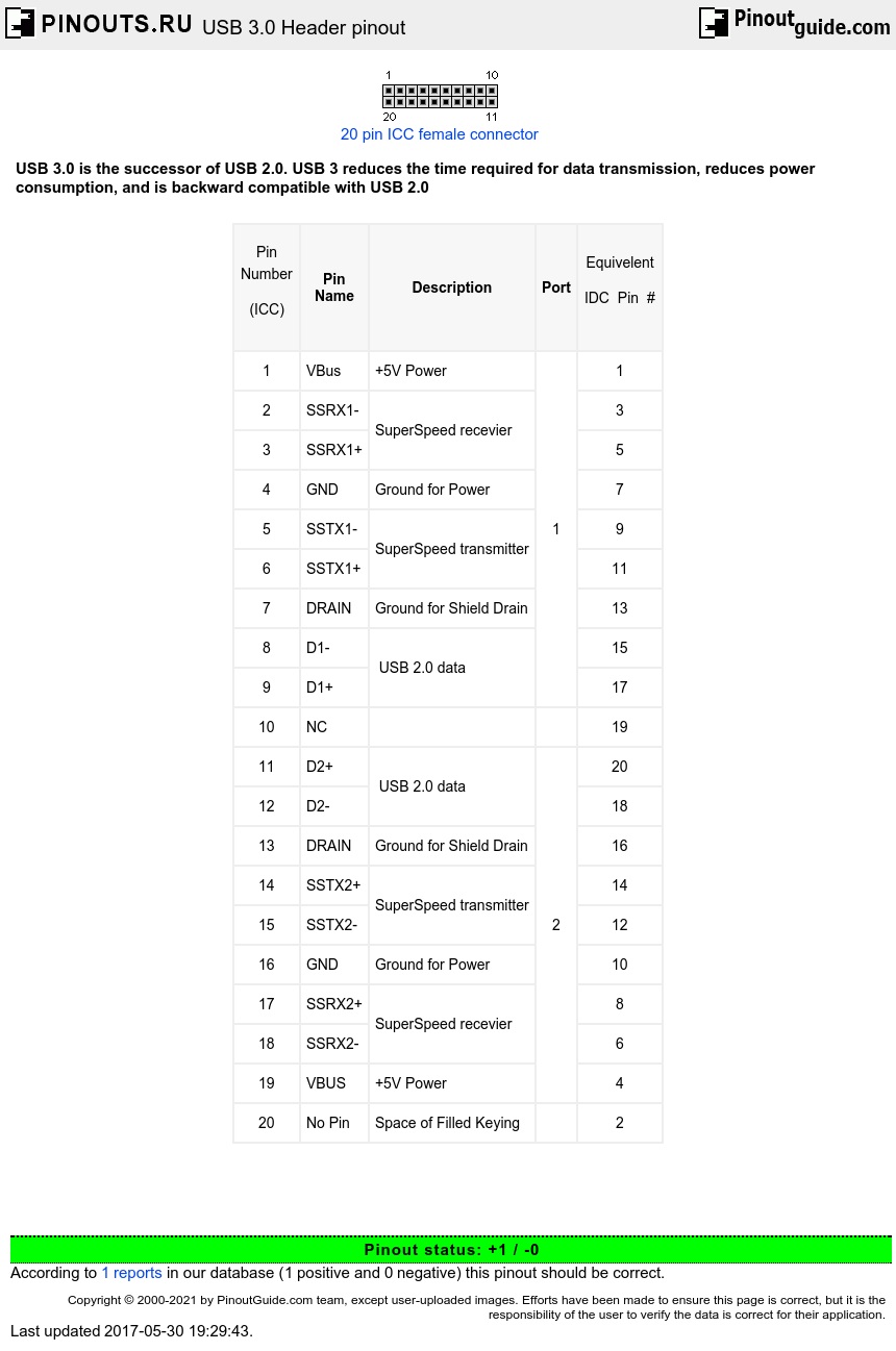
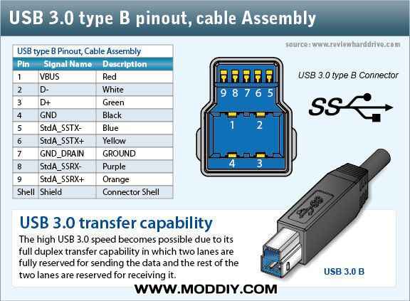
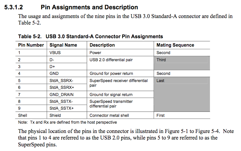
Unlike usb2 this links are fully separated no shared shield and two single links can be inserted into the header connector. Usb 30 interconnect topology with internal cable alternatively the internal cable assembly may directly connect to the external usb ports the standard a connectors without the daughter card. Usb 3 pinouts and signals. Like the usb 20 header the usb 30 header contains usb 30 ports. The cable has the original 4 wires of the usb 20 specification dd power ground plus the one added by the usb 30 specification. Usb 30 combines usb 20 bus and new superspeed bus with transfer rate up to 50 gbits which is about ten times faster than the usb 20 standard.
Usb 30 connectors are usually distinguished from. Typically it uses black green white and red wire colours. The usb cable provides four pathways two power conductors and two twisted signal conductors. Black cable serves as floor just like in every other device. According to usb 30 pcb wiring diagram you will find only four wires used inside the cable. Usb 30 is the third major version of the universal serial bus usb standard for interfacing computers and electronic devices.
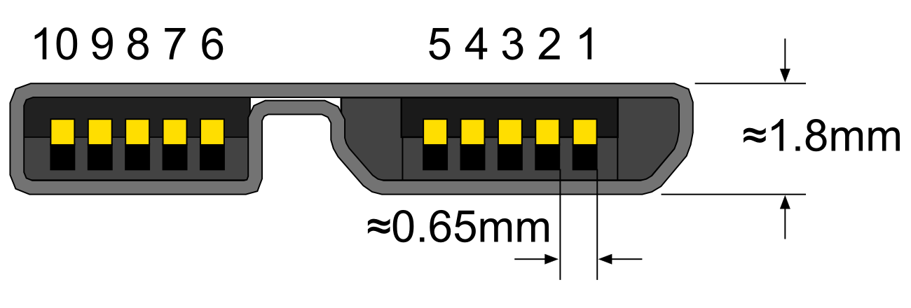
Usb 30 connectors are. The usb 30 specification is the combination of the physical superspeed bus combined in parallel with the physical usb 20 bus. The usb 30 specification adds two sets of shielded differential paired wires labeled as sdp. The header has a key slot on the pin 1 10 side if enclosed. Usb 30 header is a 20 pin 2mm pitch header using the less common icc pin numbering. Obsidian usb 3 soundboard wiring diagram there are several kinds of electronic gadgets out there.
Unsubscribe from varun kumar. Usb 30 wire diagram varun kumar. The cable may be utilized to transfer data from 1 apparatus to another. The red one is for positive cable with dc power of 5 liter. Most of them use usb cable. The data is transferred through the d and d connectors while vbus and gnd connectors provide power to the usb device.
Usb 30 combines usb 20 bus and new superspeed bus with transfer rate up to 50 gbits which is about ten times faster than the usb 20 standard. Usb 30 cable diagram. Figure 1 1 illustrated the usb 30 interconnect topology.
Gallery of Usb 3 0 Wiring Diagram