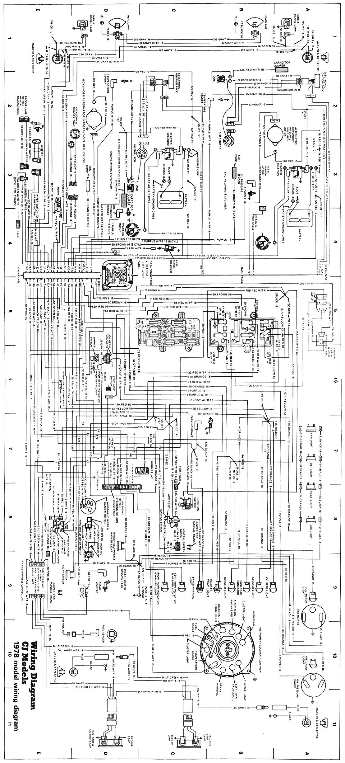
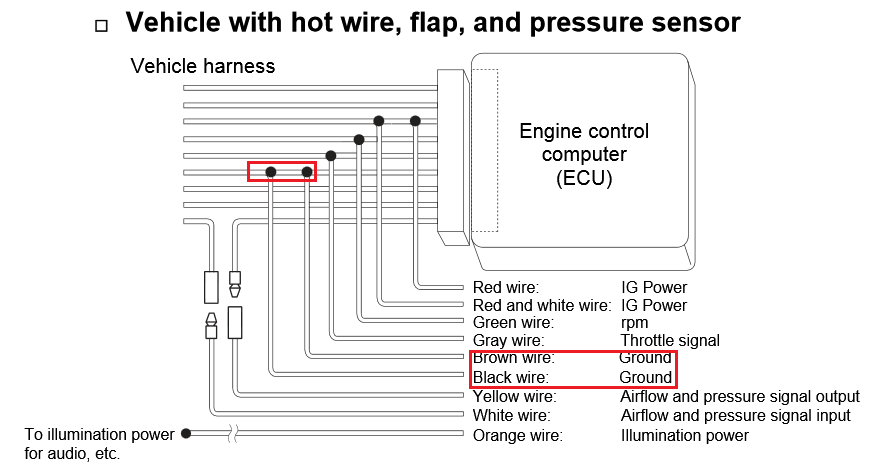
Add thread to del. The diagram above actually tells you where to wire them on the car.

Apexi Safc 2 Manual En Espanol
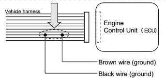
Vafc 1 wiring diagram. Caution 2locate the engine control unit hereafter referred to as ecu of the vehicle by referring to the wiring diagram by model. For application to vehicles released after that consult. Failure to do so may result in engine damage. Vafc harness vtec solenod signal purple pare gink. Basically u are using a combination of diagram h8 a and h7 b to complete the install. Wiring diagram book a1 15 b1 b2 16 18 b3 a2 b1 b3 15 supply voltage 16 18 l m h 2 levels b2 l1 f u 1 460 v f u 2 l2 l3 gnd h1 h3 h2 h4 f u 3 x1a f u 4 f u 5 x2a r power on optional x1 x2115 v 230 v h1 h3 h2 h4 optional connection electrostatically shielded transformer f u 6 off on m l1 l2 1 2 stop ol m start 3 start start fiber optic.
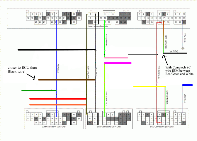
Vafc 1 wiring diagram manual whats apexj vafc 1 wiring diagram manual well my motivations were as follows 1 to keep myself occupied at home finding which wire does what in a manual free wa we had to wrestle with aexi wiring though not only because we. Female fttng solenoid vehicle side side ecu side 7 connect the vtec afchamess wire to the connector in 6. Vtecsoienoid wire connection male fifing. 1 in the wiring diagram it says to ground the vafc brown and black wires to ecu ground with the brown wire spliced closer to the ecu than the black wire. Page 18 third edition 26 jun. 3connect the harness attached to the v afc ii securely to the power cable of the vehicle.
The vafcii display should now be active. I have the wiring diagram and i am pretty much ready to go but have a couple of questions. Connecting the vafc ii 1remove the negative terminal of the battery. Need apexi vafc 1 pdf instructions honda tech honda forum discussion. This diagram is only for showing what each color means and whether the wire should be cut or spliced. 6 refer to the vehicle sbecific wiring diagram on p16 and cut the vtec solenoid signal wpre gong to the ecu and add the connectors.
Gallery of Vafc 1 Wiring Diagram