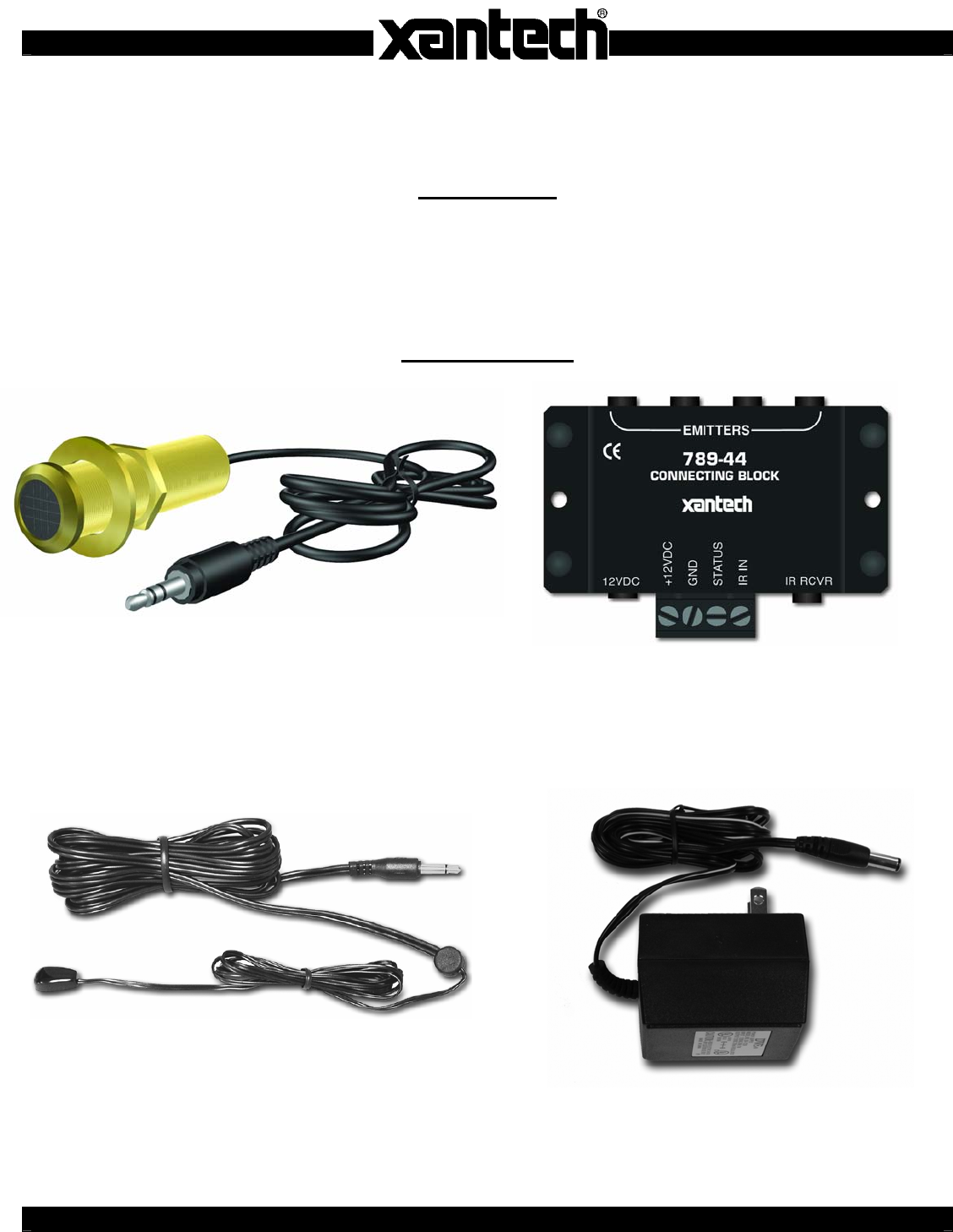
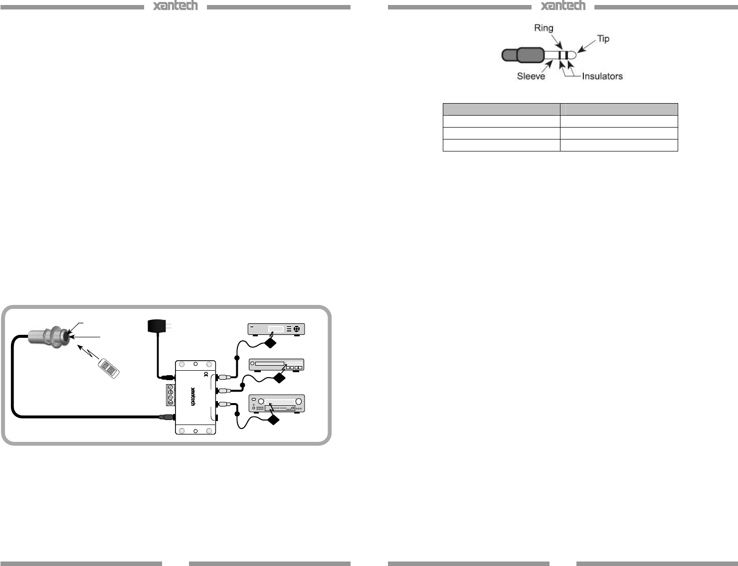
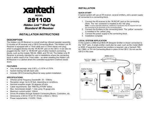
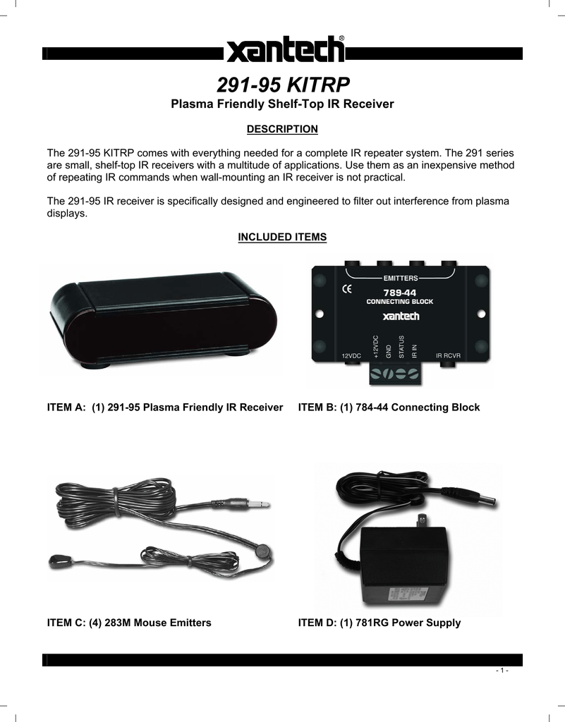
The ir rcvr jack on the 789 44 allows the 490 30 and other xantech ir receivers with a cable having a 35 mm stereo mini plug to be plugged directly into the 789 44. Xantech 789 44 features at a glance.
72 48095 Installation Instructions User Manual
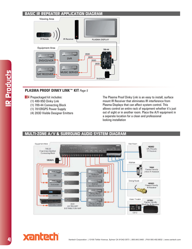
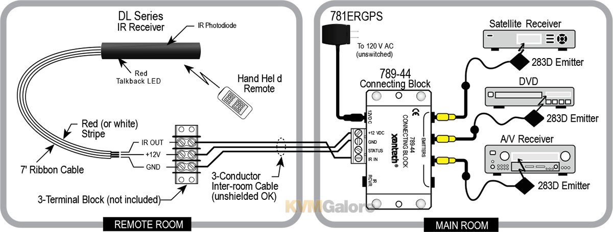
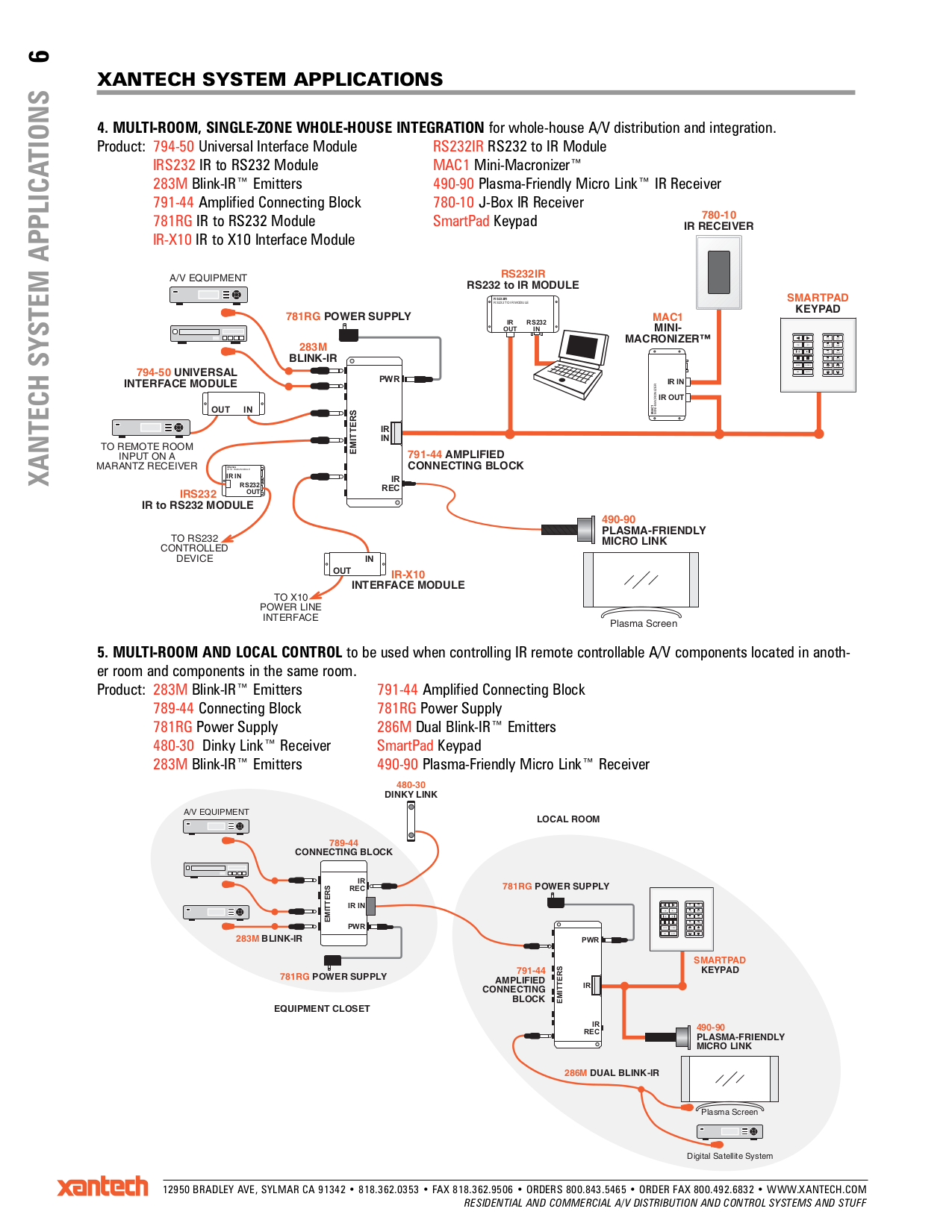
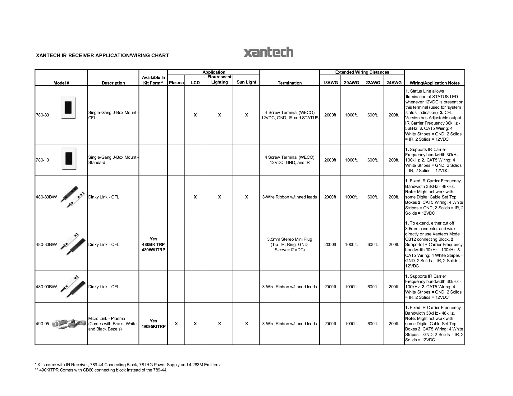
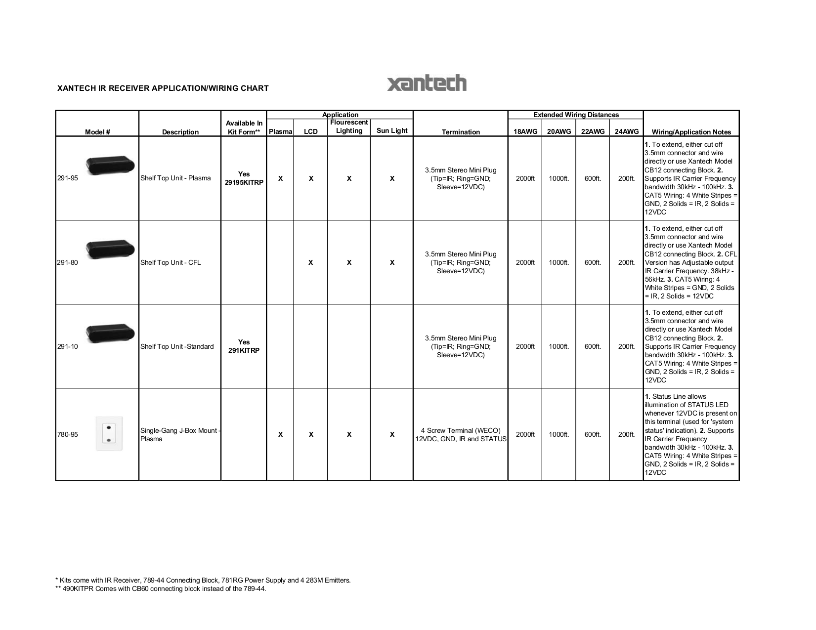
Xantech 789 44 wiring diagram. When configuring a system please keep the following items in mind. Signal wire between ir receiver and the connecting block is open. Xantech 789 44 wiring diagram. One zone four source connecting block. Bayliner capri wiring diagram. Instance in the diagram below an optional 791 44 connecting block is used to control several components.
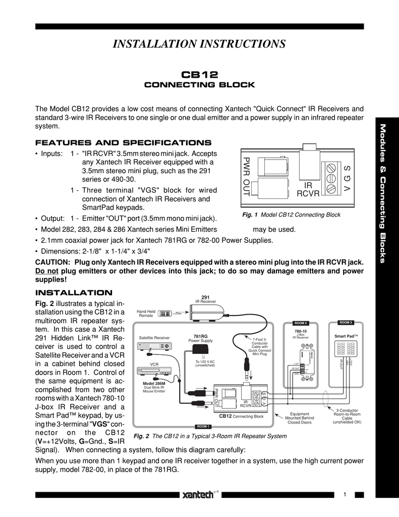
Coleman heat pump thermostat wiring diagram. A variety of xantech ir receivers and a keypad are shown. L5 30r receptacle wiring diagram. Connect the plug in the 21mm coaxial power plug of the 781rg power supply not included into the jack labeled 12vdc on the 789 44 connecting block. Emitters on the 789 44 and affix the opposite end to the ir sensor window of the controlled equipment. John deere lx173 wiring diagram.
Human female organ diagram. Test emitter and verify wiring. No wiring extension should be required so long as the connecting block is within reach. To 120 vac unswitched emitter. Ir rcvr jack on the xantech connecting block. Connects four emitter ports and power supply to all xantech infrared receivers and keypads.
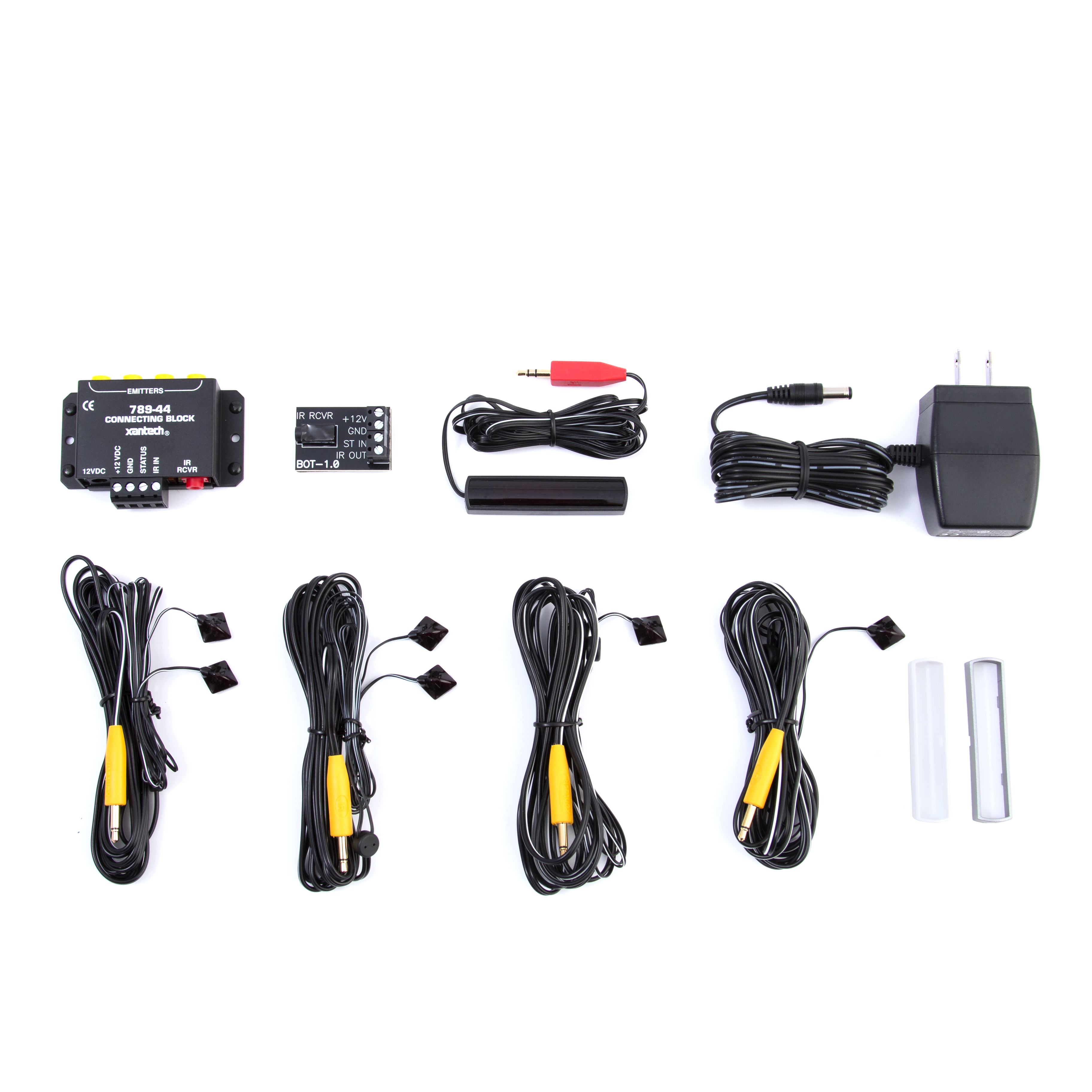
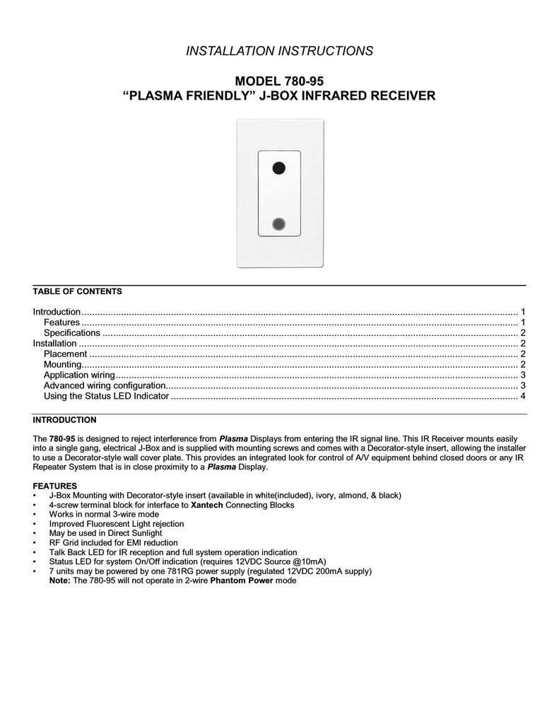
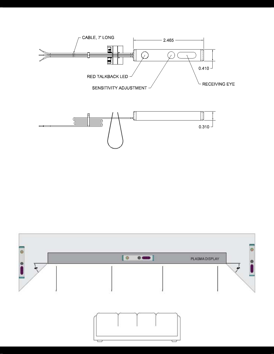
Includes 789 44 connecting block power supply and four 283d emitters for easy system installation. Plug the ac end of the 781rg power supply into an un switched 120v ac line outlet. Placement the ir receiver should be located so that it is not directly facing a light source. Four parallel emitter ports with 470 ohm resistors drive four single or four dual emitters. Door entry phone wiring diagram. Xantech 789 44 connecting block.
Gallery of Xantech 789 44 Wiring Diagram