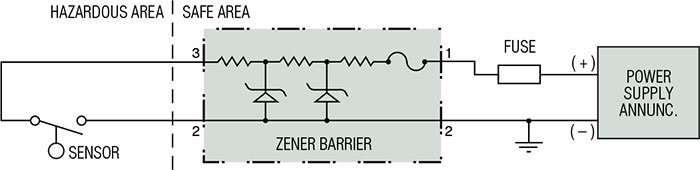
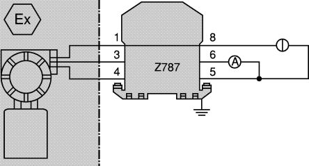
Circuit of the connecting wiring in the hazardous area or a connection to earth of the wiring attached to terminal 1 as the fuse blows. Zener diode circuit for psu with series transistor.
Pepperl Fuchs 2 Channel Zener Barrier With Analogue Output 250 V Max 120ma Max
Zener barrier wiring diagram. To ensure the safety of such a wiring point t1 must be connected to ground as illustrated in fig. The simple circuit diagram is displayed below where the transistor is being used as emitter follower. The above shown simple shunt regulator is not mostly effective and not feasible for higher current applicationz. The operating range of a zener barrier must therefore be such that it is below the zener voltage so that the leakage current is restricted to a minimum. Typical intrinsic safety barrier wiring diagrams i. Sensor switch hazardous location non hazardous area 32 1 non hazardous area hazardous area sensor.
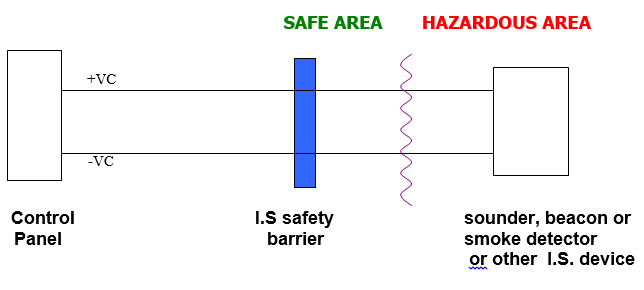
A zener barrier is an associated equipment that is installed in the safe area. However since its primary use is in. Rl ac input source zener barrier input power from source not greater than 250 vac stud cover must be in place when barrier is in use. It is designed to limit the amount of energy that could appear in an electrical circuit passes through the hazardous area despite the connection before the barrier. Switches 8 7 6 5 4 3 2 1 term. The way out of it is to use a zener diode circuit with a seris pass transistor.
Zener barriers the applied voltage is increased. By cust v com. Zener barriers operating instructions. Zener barriers are normally tested to check that at the prescribed voltage the leakage current is smaller than 10 µα. Power supply 1 2 red black white 3 2 3 2 1 output 5 vdc input voltage versions warning the nature of the sensor is that it is a non voltage producing device con taining no energy storing components. Figure 11 circuit diagram if this voltage is exceeded due to a fault in the non ex area.
Zener barrier wiring diagram dc.
Gallery of Zener Barrier Wiring Diagram