Ive been working in broadcast media since 2008 and developing software and websites for just as long. Dmx 3 pin to 5 pin wiring im anthony eden and im a it professional broadcast technician software developer and solutions engineer.
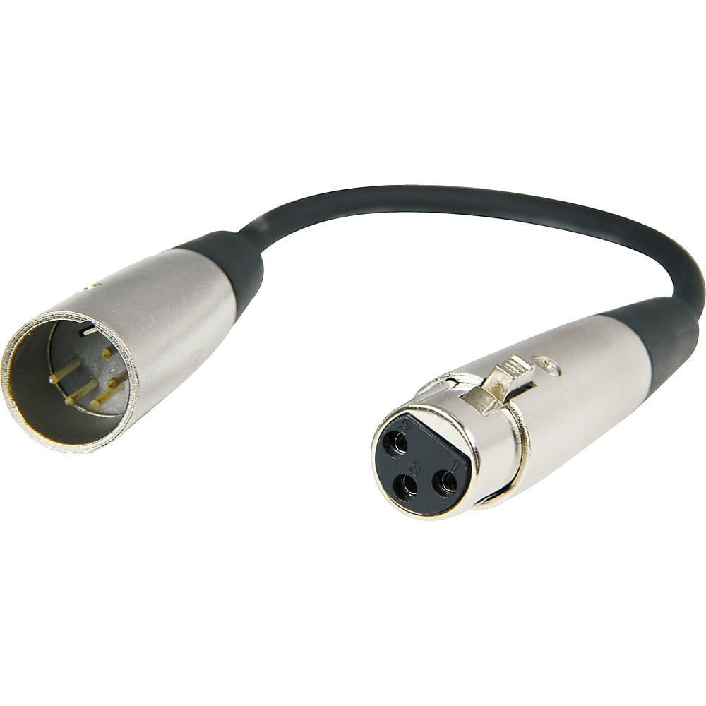
Hosa Dmx 106 5 Pin Male Xlr To 3 Pin Female Xlr Dmx 512 Adaptor Cable 6 In Walmart Com
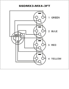
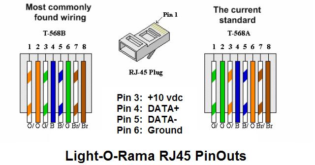
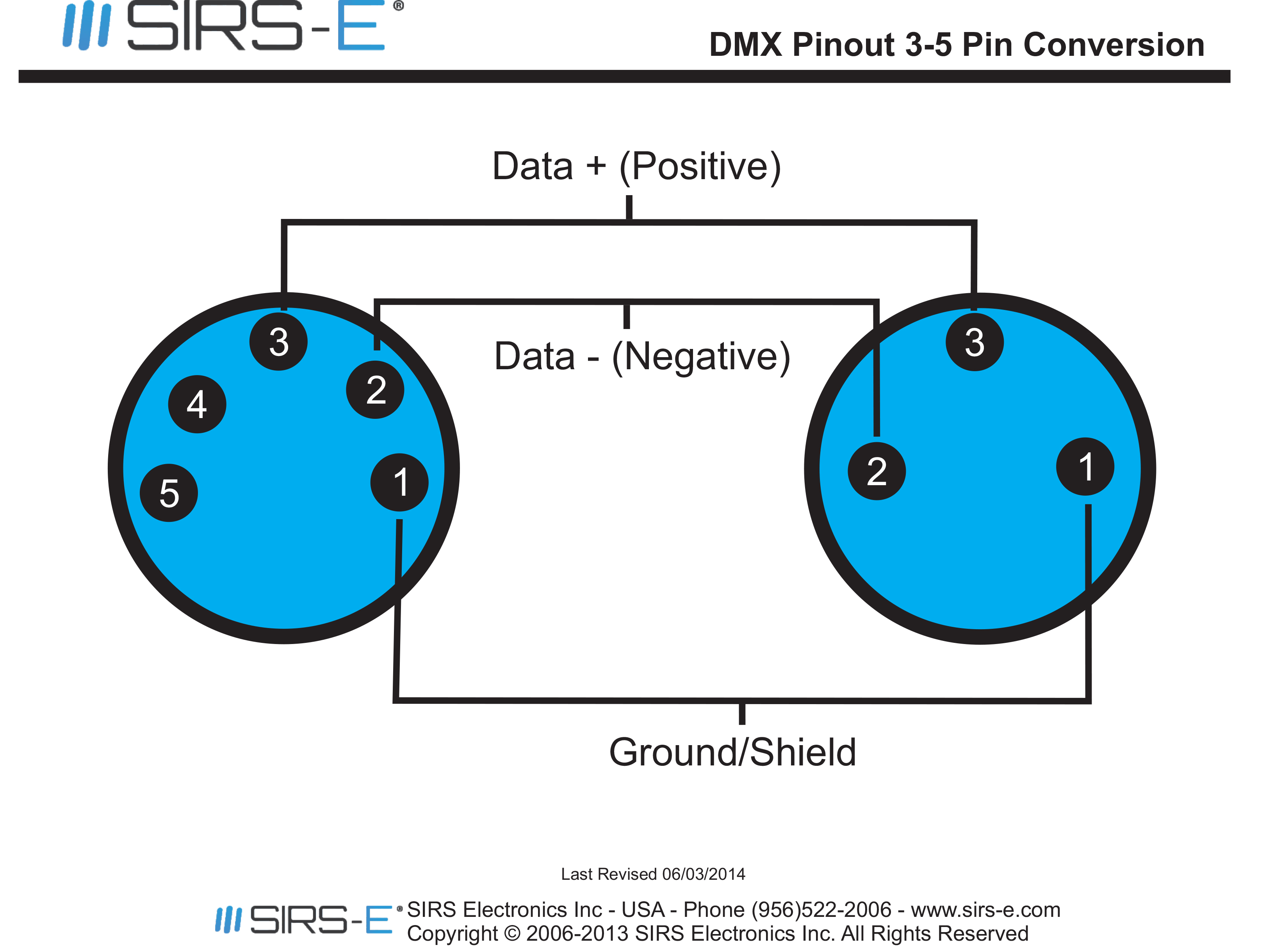
3 pin dmx wiring diagram. However there are a lot of lighting fixtures which use 3 pin xlr connectors for dmx. Dmx digital multiplex is a communications protocol used mainly to control stage lighting. This article explains how to made adaptors between 3 and 5 pin dmx xlr connectors. Rj45 connectors may be used with cat5 cable for permanent wiring. 3 pin dmx wiring diagram wiring diagram is a simplified usual pictorial representation of an electrical circuit. Per the standard dmx uses 5 pin xlr with male being input and female being output.
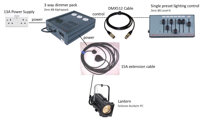
The daisy chain is a simple wiring method where you wire each fixture looping out of the previous fixture to create a line of fixtures connected back to the console. Dmx is the primary method for linking controllers dimmers advanced fixtures and special effects devices such as foggers and moving lights. Traditionally 3 pin connectors have been the domain of audio and 5 pin xlr connectors have been the domain of dmx control for lighting. Xlr connector wiring diagram together with 3 pin mini 5 pin xlr wiring diagram for center u2022 4 dmx diagrams rh gregorywein co 3 female end cable wiring xlr cable wiring diagram. How to solder the connections for a standard 3pin xlr female. Visit the post for more.
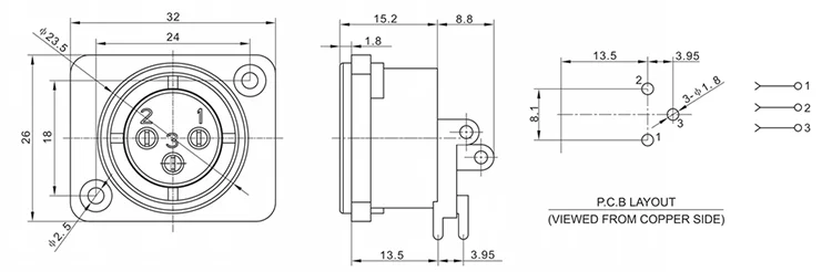
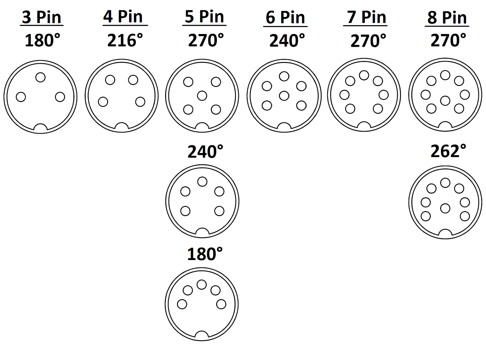
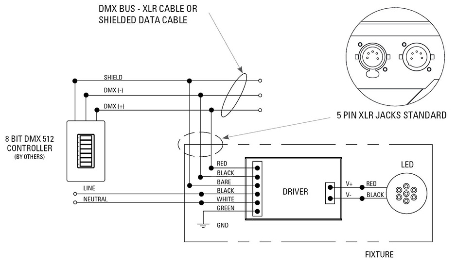
Here are the dmx 512 pinouts for each. Network wiring consists of a shielded twisted pair with a characteristic impedance of 120 ohms with a termination resistor at the end of the cable furthest from the. When working with a lighting console whether its a pc based or hardware the console will come with a dmx outputa dmx output sends out a signal to communicate with lighting fixtures. There are also numerous other connection types such as 3 pin rj45 etc. Ansi e111 2008 r2013 entertainment technology usitt dmx512 a asynchronous serial digital data transmission standard for controlling lighting equipment and accessories cp2007 1031r31. Wire must be belden 9829 9842 cat 5 or equivalent.
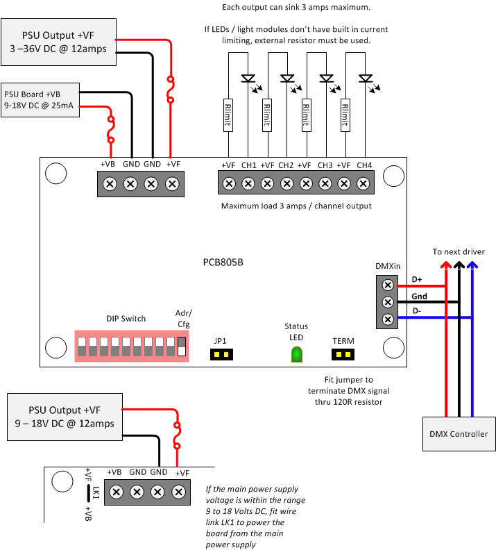
A dmx512 controller is connected to fixtures or devices in a daisy chain link. Dmx512 data are transmitted over a differential pair using eia 485 voltage levels. Cat5 utp cable may be used inside metal conduit. The last dmx device on the line must be terminated with a termination switch or resistor with a value of 100 to 120 ohms between pins 2 and 3. This is why we offer an alternative idc header to support cat5 wire on most of our dmx products. The rear view is the end you solder from here are the connections on each pin.
It shows the components of the circuit as simplified shapes and the capability and signal links in the middle of the devices. Each device has a dmx in and generally a dmx out xlr 5 pin connector sometimes marked as dmx thru.
Gallery of 3 Pin Dmx Wiring Diagram


.jpg)