4 wire ceiling fan switch wiring diagram. It reveals the elements of the circuit as simplified shapes and the power and signal connections between the tools.

Planet Analog 4 Wire Current Loop Sensor Transmitters
4 wire wiring diagram. 800 x 600 px source. A wiring diagram is a streamlined traditional pictorial representation of an electrical circuit. 5 wire trailer plug 7 prong trailer wiring 4 size. Honeywell thermostat wiring diagram 4 wire. Wall plate for a 4 wire smart thermostat installation. 4 way tow vehicle side.
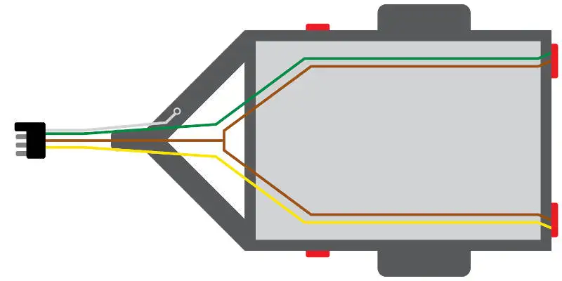
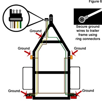
Adjoining cable paths may be shown about where particular receptacles or components must be on an usual circuit. In the seymour duncan sh 4 jb wiring that well be doing the pickup is installed using four colored conductor wires and a bare wire. You must check the trailer manual to see if the wiring is correct but normally the white wire is called the ground wire while the brown wire is used for tail lights. Right turn signal stop light green left turn signal stop light yellow taillight license side marker brown and a ground white. Collection of 4 wire ceiling fan switch wiring diagram. To view it at full size click on the diagram.
This diagram is a thumbnail. Honeywell thermostat wiring diagram 4 wire. Click here to access note. Trailer wiring diagrams 4 way systems 4 way flat molded connectors allow basic hookup for three lighting functions. For complete instructions on wiring a basic 4 way switch see our wiring a 4 way switch article. 4 wire oxygen sensor wiring diagram fresh audi a4 oxygen sensor building circuitry diagrams show the approximate locations and also affiliations of receptacles illumination and also permanent electric solutions in a structure.
This 4 way switch diagram 2 shows the power source starting at the fixture. Commonly used green white yellow and red thermostat wires. Assortment of 5 wire to 4 wire trailer wiring diagram. Installing the 4 pin trailer wires. This one uses the green wire as the c wire instead of the g fan wire. It shows the components of the circuit as streamlined shapes and the power and signal connections between the devices.
A wiring diagram is a streamlined standard pictorial depiction of an electrical circuit. The white wire of the cable going to the switch is attached to the black line in the fixture box using a wirenut. 4 way switch wiring diagrams this 4 way switch diagram 1 shows the power source starting at the left 3 way switch. The 4 way is used when you want to control the light or lights from two or more locations. February 28 2019 by larry a. Seymour duncan sh 4 jb wiring diagram in this post were going to show you how to install the seymour duncan sh 4 jb humbucker pickup into your guitar.
Gallery of 4 Wire Wiring Diagram