The terminal layout for frame size r3 which in general applies to frame sizes r1r6 except for the r5r6 power and ground terminals. Application macros and wiring 6.
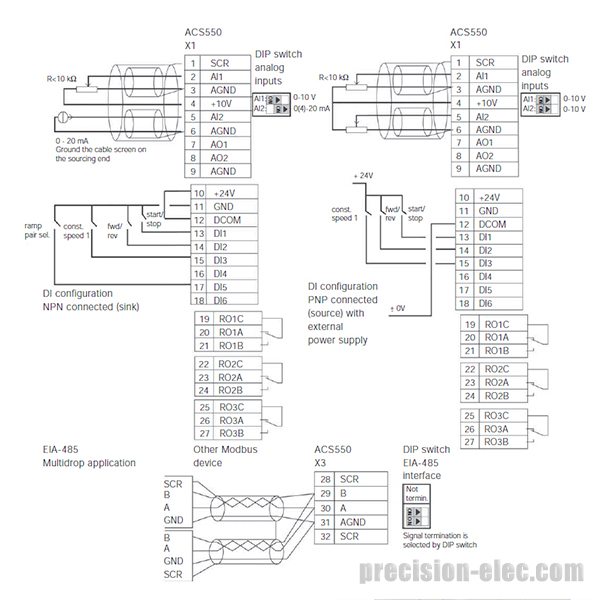
Abb Drive Ach550 Wiring Diagram Kafelena 2 Rmnddesign Nl
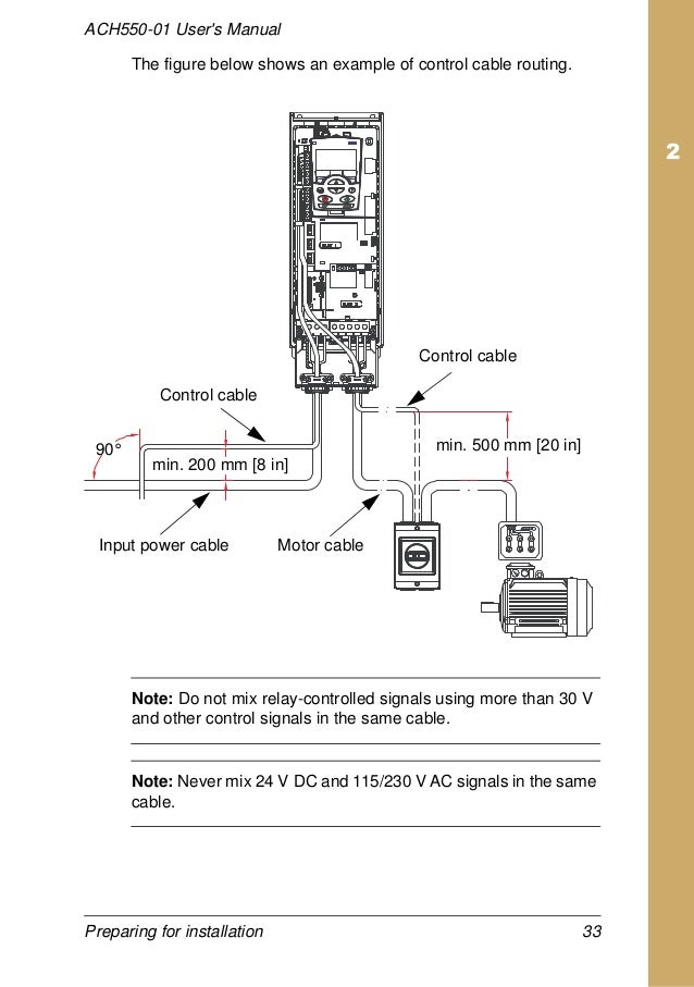
Abb ach550 wiring diagram. Tie shield wires together at drive do not terminate at scr. Abb ach550 wiring diagram building circuitry representations show the approximate places and also interconnections of receptacles illumination and also irreversible electrical services in a structure. Real time clock and timed functions 7. Never connect line voltage to drive output terminals t1 t2 and t3. Providing feedback on abb drives manuals 471. Do not connect or disconnect input or output power wiring or control wires when power is applied.
Ach550 01 users manual table of contents 5. Refer to the ach550 uh users manual for control connections to the drive. Set switch j2 to off. Ach550 01 users manual 3afe68258537 english hvac info guide 3afe68338743 english. Do not make any voltage tolerance tests hi pot or megger on any part of the unit. Bp0056 ach550 input power ground lug.
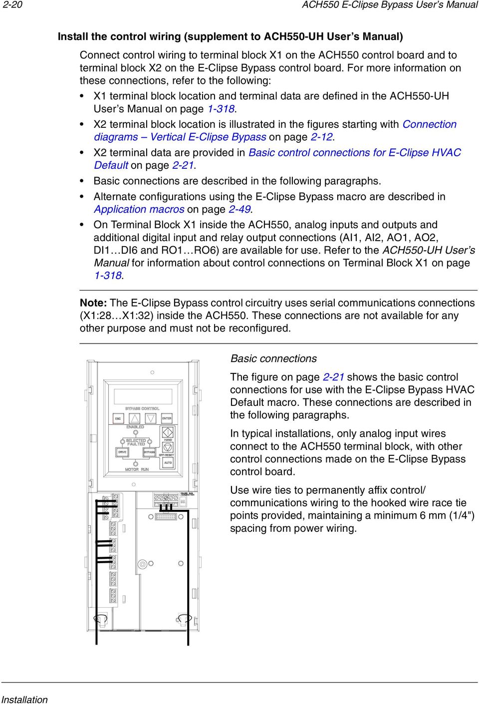
When using direct speed reference in auto mode or process pid see on page 1 49. Installing the wiring supplement to ach550 uh users manual warning. Connection diagrams standard e bypass r7r8 floor mounted ach550 standard e bypass units are configured for wiring access from the top. The following figure shows the standard e bypass floor mounted wiring connection points. The terminal layout for r7r8. The r5r6 power and ground terminals.
Bus termination is an active network. Factory defaults can be restored at any time by setting parameter 9902 to 1. Parameter listing and descriptions. 3 conductor with. 1 51 hvac default macro this macro provides the factory default parameter settings for the ach550 uh. The goal of this course is to provide participants with the required theoretical knowledge to read and use the wiring diagrams in the right manner.
Notes draw attention to a particular condition or fact or give information on a. The diagram below shows typical wiring using this macro. Ach550 uh users manual 1 3 safety safety use of warnings and notes there are two types of safety instructions throughout this manual. Collection of abb ach550 wiring diagram. 8 ach550 installation operation and maintenance manual ach550 uh connection diagrams the following diagrams show. It shows the parts of the circuit as streamlined forms and the power and also signal links in between the tools.
A wiring diagram is a simplified conventional photographic representation of an electric circuit. Pull up pull down bias resistors are on board the ach550 drive. Terminate agn wire at reference terminal in the building automation controller. Interconnecting wire paths may be revealed about where particular receptacles or fixtures should get on a common circuit.
Gallery of Abb Ach550 Wiring Diagram