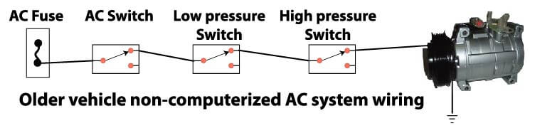
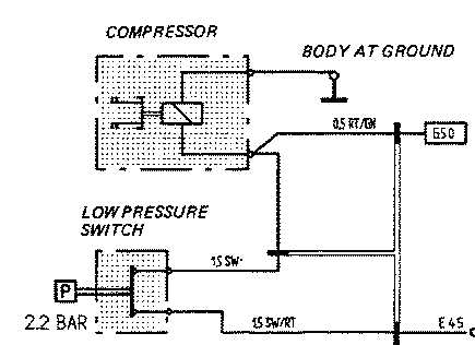
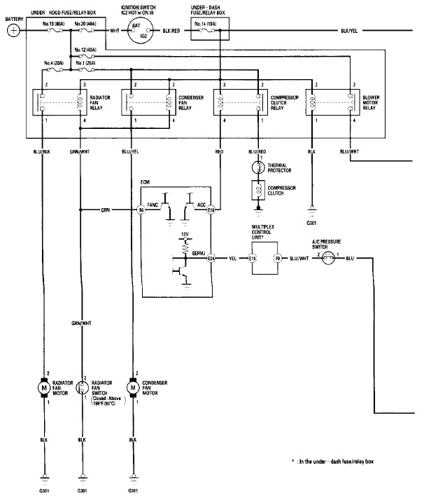
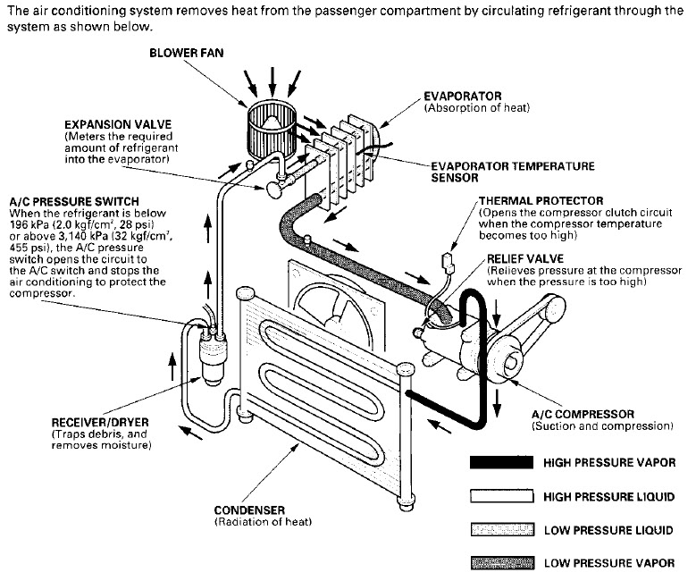
Ac compressor suction and compression ac condenser radiation of heat ac pressure sensor triple function when the refrigerant is below 196 kpa 20 kgfcm2 28 psi or above 3140 kpa 32 kgfcm2 455 psi the ac pressure switch opens the circuit to the ac switch and stops the air conditioning to protect the ac compressor. This diagram is to be used as reference for the low voltage control wiring of your heating and ac system.
Wiring Diagram For Ac System Tacoma World
Ac compressor wiring diagram. It reveals the elements of the circuit as simplified shapes as well as the power and signal connections in between the tools. Moreover the heat source for a basic ac system can include heat strips for electric heat or even a hot water coil inside the. Air conditioning repair how to ohm a compressor duration. Most models use a green wire for this connection as it has become an industry standard. A wiring diagram is a simplified traditional pictorial depiction of an electric circuit. It shows the components of the circuit as simplified shapes and the power and signal connections between the devices.
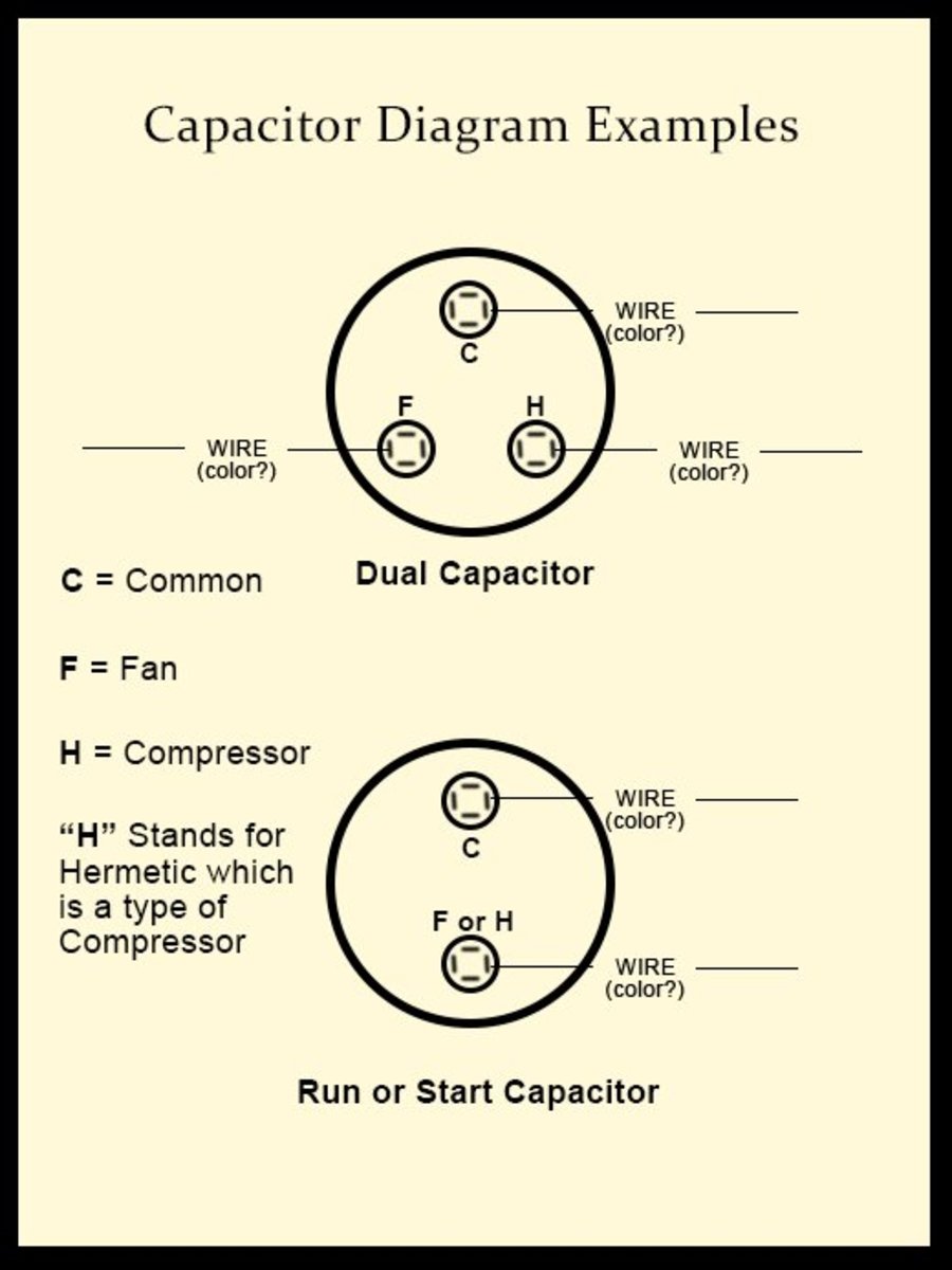
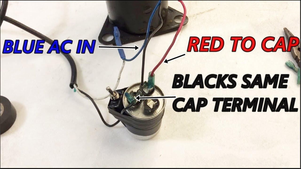
Variety of ac compressor wiring diagram. Always refer to your thermostat or equipment installation guides to verify proper wiring. Connect the red wire leading to the capacitor to the start terminal. Notesome ac systems will have a blue wire with a pink stripe in place of the yellow or y wire. The overload might be internally located in the compressor. A wiring diagram is a streamlined standard photographic representation of an electric circuit.
How to wire an air conditioner for control 5 wires the diagram below includes the typical control wiring for a conventional central air conditioning systemfurthermore it includes a thermostat a condenser and an air handler with a heat source. Word of advice tv 43716 views. Kirk giordano plastering inc. How to wire air conditioner compressor duration. The white common line is connected in series with an overload switch that protects the compressor from overheating. Plastering a new finish coat sand finish and texture plastering tips to minimize cracking stucco duration.
Typically a solenoid attached to the throttle is activated when the system is turned on and the lead from this component will power the compressor clutch. The black wire leading to the load side of the contactor is connected to the run terminal. Collection of central air conditioner wiring diagram. Consult the wiring diagram for the model locating the green wire that is coming from the throttle area.
Gallery of Ac Compressor Wiring Diagram