The brake control terminals udc udc r and r terminals carry a dangerous dc voltage over 500v. 1974 f100f350 8 pages complete 3259 x 2400 765k 3547 x 1955 902k page 03 3817 x 1936 980k page 04 3786 x 2279 918k 3790 x 1887 861k 3771 x 2269 994k 3786 x 2267 866k 3803 x 2268 529k.

Programming Escherichia Coli To Function As A Digital Display
Acs 600 wiring diagram. The acx 600 motor cable terminals are at a dangerously high voltage when power is applied regardless of motor operation. 3ø wiring diagrams 1ø wiring diagrams diagram er9 m 3 1 5 9 3 7 11 low speed high speed u1 v1 w1 w2 u2 v2 tk tk thermal overloads two speed stardelta motor switch m 3 0 10v 20v 415v ac 4 20ma outp uts diagram ic2 m 1 240v ac 0 10v outp ut diagram ic3 m 1 0 10v 4 20ma 240v ac outp uts these diagrams are current at the time of publication. For continuous operation around 350 volts is. There can be dangerous voltages inside the acx 600 from external control circuits when the acx 600 input power is shut off. There can be dangerous voltages inside the acs 600 from external control circuits when the acs 600 mains power is shut off. Appendix a contains basic circuit diagrams for acs 600 multidrive modules components.
Motors of this type are suited for air conditioning and refrigeration applications belt driven fans etc. For acs 600 multidrive modules components. Alldatas wiring diagram schematics are taken directly from original equipment manufacturer oem service manuals and made interactive for ease of use. Strikes magnetic locks readers and inputs. Do not attempt any measurement parts replacement or other service procedure not described in this manual. We are the leading source of professional diagnostic and repair information used by over 75000 repair professionals.
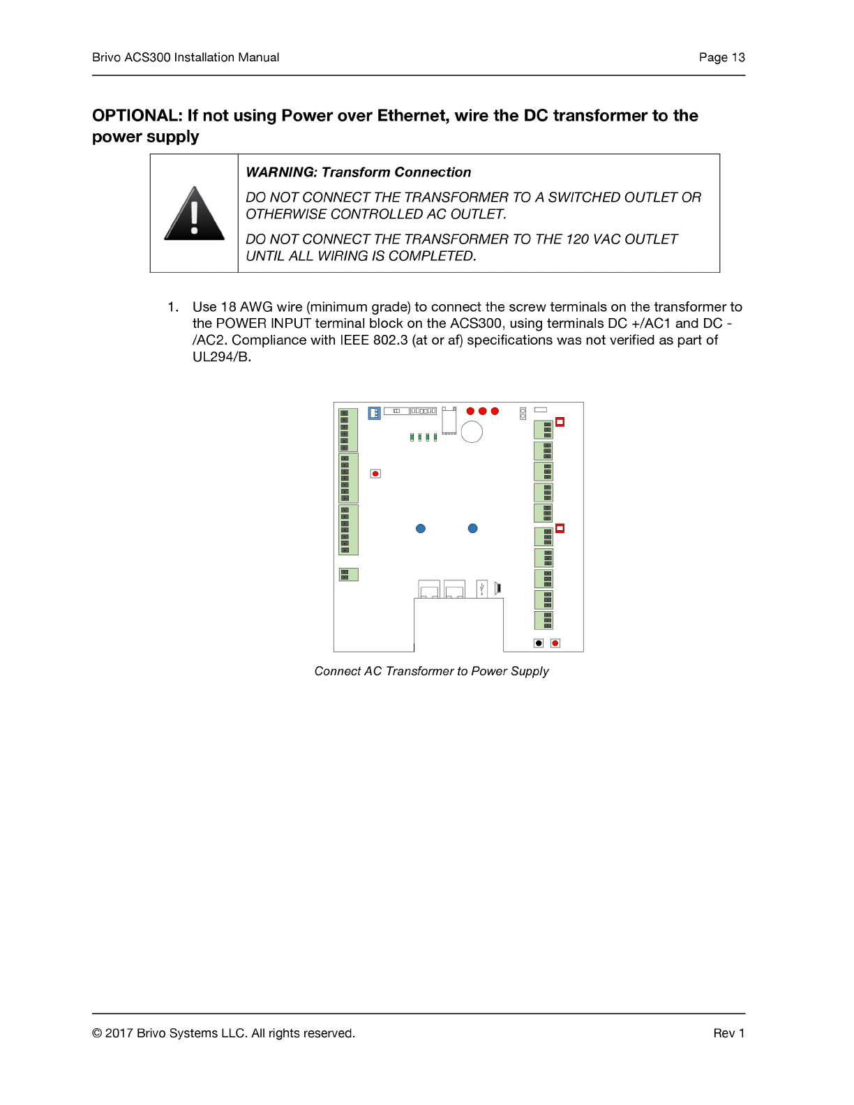
Chapter 3 includes control wiring examples and instructions. Wiring diagrams of small and fractional horsepower electric motors. You can purchase access to the mercedes benz data in one or five year. 1975 f100f350 10 pages complete. The voltage supplied to the capacitor by means of the transformer can vary between 600 and 800 volts during start up. 1973 1979 ford f series truck wiring diagrams.
What this manual contains chapter 2 gives instructions for building the cabinet eg. For specific instructions on whenhow to change control boards or their wiring or power plates refer to acs 600 service manual en code. Ls f60g60 and ls n100s100 readers wiring diagram. Cooling emc compliance and for installing the components. Wire data102 electrical formulas103 104 list of tables table 1 standard elementary diagram symbols 1 table 2 nema and iec terminal markings 4 table 3 nema and iec controller markings and elementary diagrams 4 table 4 control and power connections for across the line starters 600 v or less4 table 5 motor lead connections 64. Exercise appropriate care when working with the unit.
Ls 100 and ls 200 strikes wiring diagram. The acs 600 motor cable terminals are at a dangerously high voltage when mains power is applied regardless of motor operation.
Gallery of Acs 600 Wiring Diagram


%2C445%2C291%2C400%2C400%2Carial%2C12%2C4%2C0%2C0%2C5_SCLZZZZZZZ_.jpg)