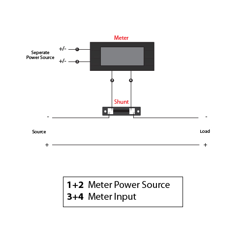
Cts are not polarity sensitive. Ac meter terminals there are two terminals on the back of the meter marked and.
In Car Amp Meter
Analog amp meter wiring diagram. A wiring diagram is a simplified traditional photographic representation of an electric circuit. On ac meters these markings can be disregarded. On dc meters these markings refer to positive and negative. Most boats make provisions in their wiring for adding in an ammeter. Assortment of volt amp meter wiring diagram. It is recommended that insulated wire terminals preferably ring type be used on all connections to the ammeter.
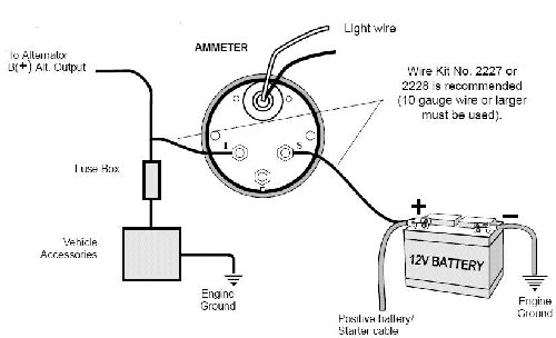
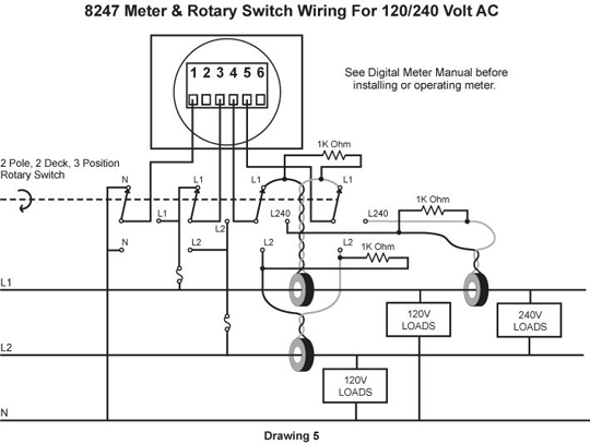
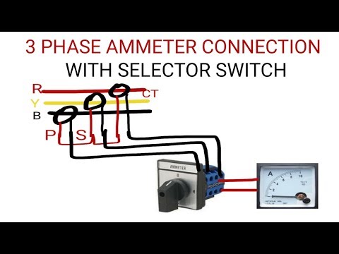
Connect ammeter lamp 60 0 60 i only to existing instrument panel lighting circuit. Wiring diagram ac ammeters pn 8258 pn 9630. Meter that works with the integrated amplifier circuitthe signal will sound the audio amplifier circuit into vu meter continue reading search for. Ct negative terminals are referenced to the meters neutral and may be at elevated voltages. Bought an ammeter and shunt from china with no instructions how to wire it. Wiring diagram dc ammeter installation continued title.
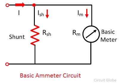
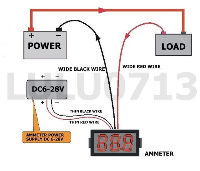
In below diagram i shown that how to wire amp meter in the diagram i shown two wire coolers in which one is black and second is red. Analog dc ammeters with external shunt 0 50a 0 75a 0 100a 0 150a 0 200a. You called this black and red cooler wires positive and negative for dc direct current or you can also called these coolers neutral and phase for ac alternative current. Reconnect the battery ground cable. Wire sizing chart standard meter micro meter. Do not connect or short other circuits to the ct terminals.
No need to observe orientation. Standard meters analog ac ammeter. The easiest way to do this is to mark where you want the meter in your lid take measurement of the size of hole needed different for all meters and drillcut the hole or make a external holder for the ma meter. Ill show you how. Connection blue sea systems ammeters of 50 ampere and greater capacity utilize. If ammeter shows a positive charge when starter is engaged reverse connections on back of ammeter.
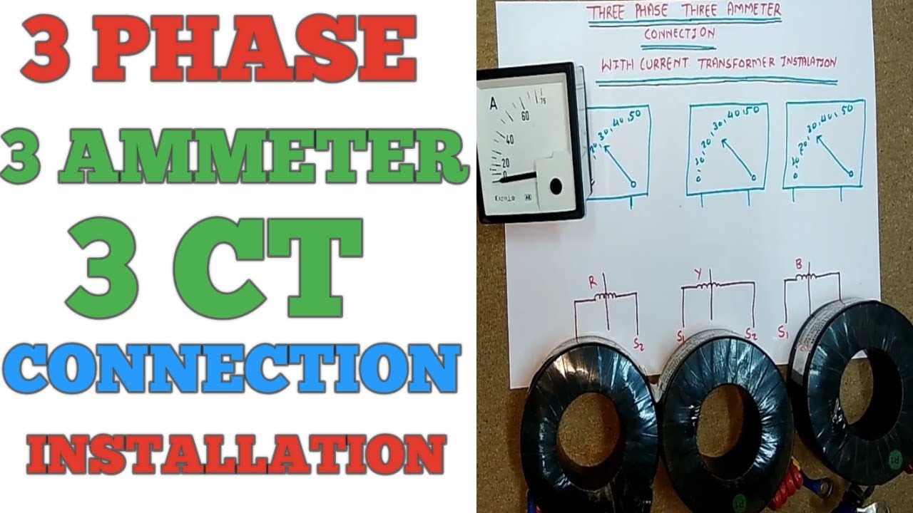
Do not contact meter terminals while unit is connected. The negative wire comes from the tube to the input on the meter and output from the meter going back to the l on the power supply. It reveals the elements of the circuit as simplified forms and the power and signal connections between the devices. 1 phase line to neutral 2 wire system 1 ct. In this video i show how to properly wire an ammeter amp gauge with a shunt to measure amps. Be certain to use stranded insulated wire not lighter than 10 awg that is approved for marine use.
Gallery of Analog Amp Meter Wiring Diagram