Days one apfc panel cannot be used for different application. Power factor can be defined as the ratio of apparent energy to active energy and an important factor in measuring power consumption is the fact that everyone knows how much electricity is available today.
2487 Vfd Starter Panel Wiring Diagram Wiring Resources
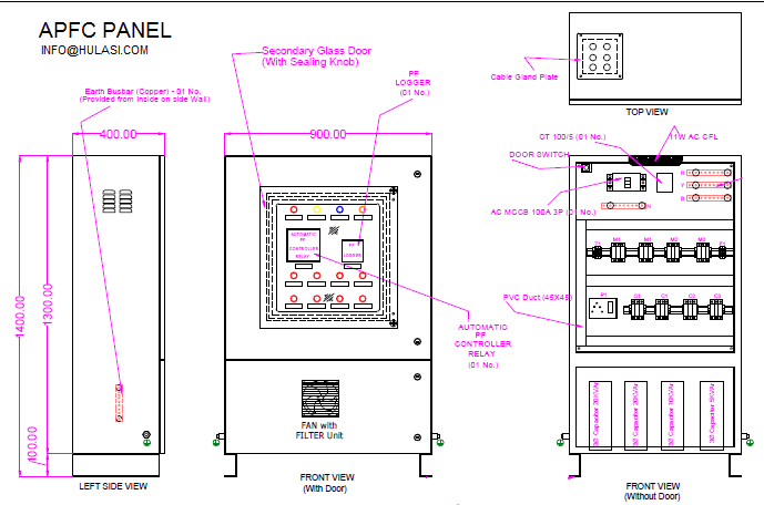
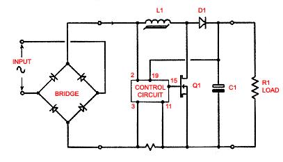
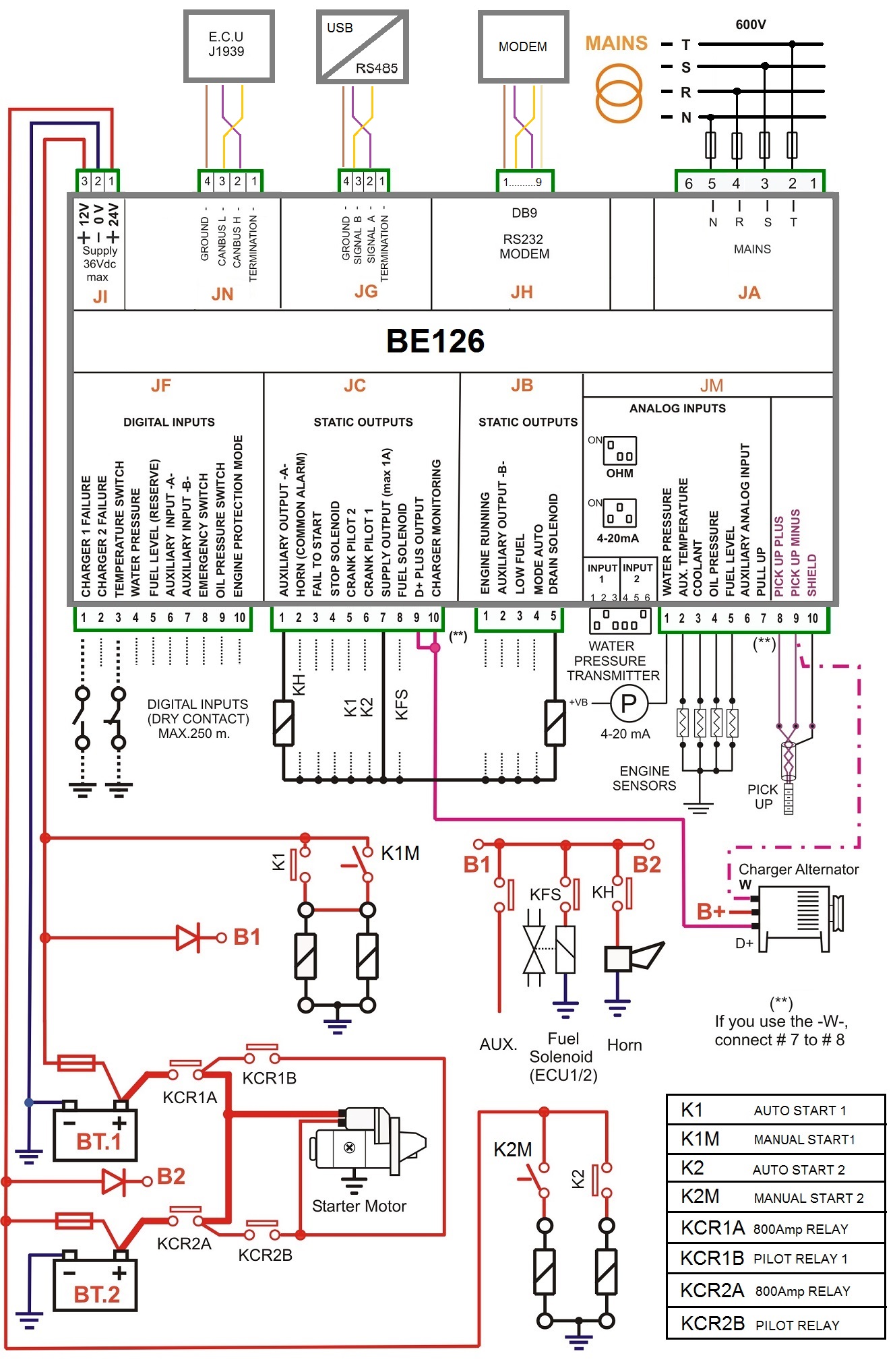
Apfc control wiring diagram. Apfc panel control wiring diagram how to do control wiring of auto power factor correction panel electrical infinity. It is used to improve power factor to meet the current requirement to reduce the billing and also to improve feeder voltage regulation. Automatic power factor control apfc relay apfc control wiring wiring diagram apfc control circuit. Refer fig no 3 figm. That photograph apfc relay control wiring diagram apfc panel wiring diagram pdf within relay panel. Apfc panel wiring explained in detail.
3 phase db wiring diagram with mcb connection duration. Apfc stands for auto power factor correction panel. Including lighting engine stereo hvac wiring diagrams. In case there is no transformer in the installation then the ct for sensing power factor should be provided at the incoming of main switch of the plant. Free automotive wiring diagrams in full color for all cars trucks or vans. Wiring diagram book a1 15 b1 b2 16 18 b3 a2 b1 b3 15 supply voltage 16 18 l m h 2 levels b2 l1 f u 1 460 v f u 2 l2 l3 gnd h1 h3 h2 h4 f u 3 x1a f u 4 f u 5 x2a r power on.
Through the thousands of pictures on the web about relay panel wiring diagram we choices the top libraries using best quality simply for you all and now this images is actually one of images choices in your best photos gallery regarding relay panel wiring diagrami really hope you may want it. Note that apfc panel can maintain the power factor on lt side of transformer and it is necessary to provide fix compensation for power transformer refer fig no 1 5. Apfc or automatic power factor control panels are mainly used for the improvement of power factor. Typical controller markings typical elementary diagram table 4 control and power connections for across the line starters 600 v or less from nema standard ics 2 321a60. Motor control 101 duration. Control wiring diagram.
Power factor can be explained as ratio of active power to apparent power and it is a key factor in measuring electrical consumption. Get your free automotive wiring diagrams sent right to you. Apfc or automatic factor control panel panels are widely used for power factor optimization.
Gallery of Apfc Control Wiring Diagram