See all power control monitoring. It shows the elements of the circuit as streamlined shapes as well as the power and also signal links between the gadgets.

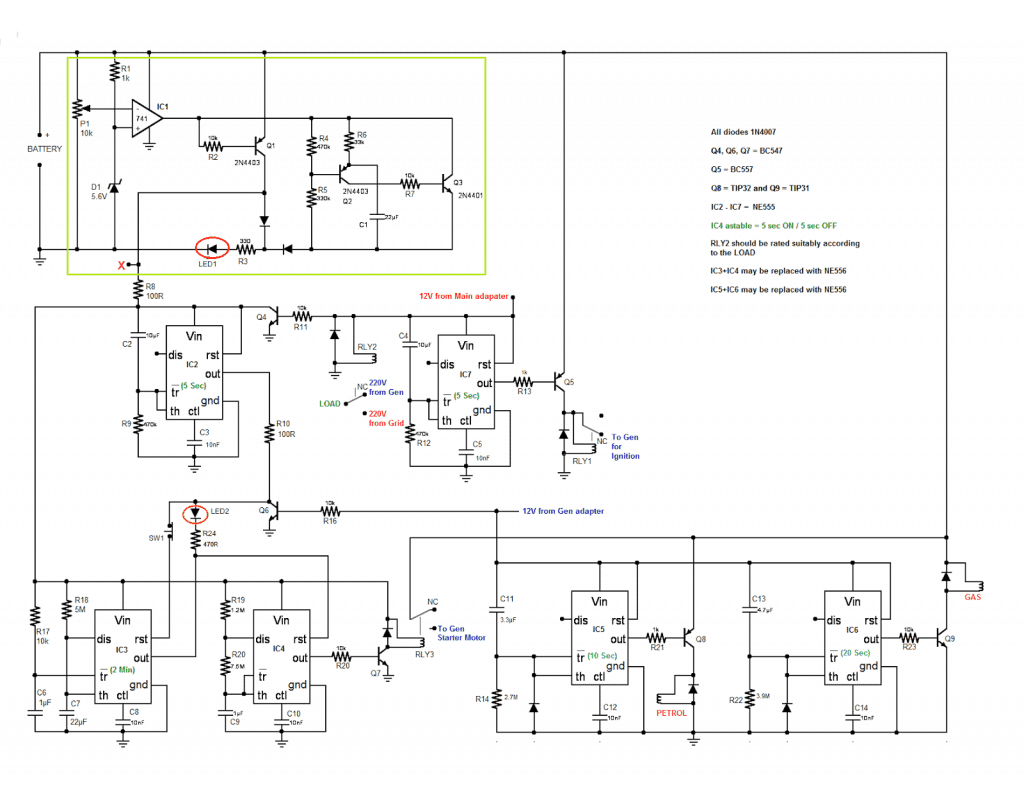
Pdf A Low Cost Generator Auto Transfer Switch Ats
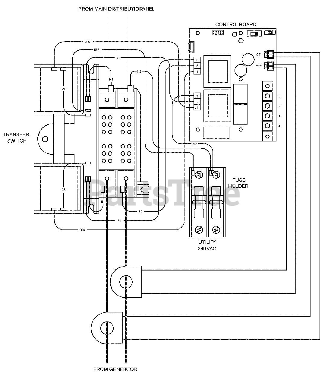
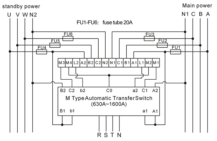
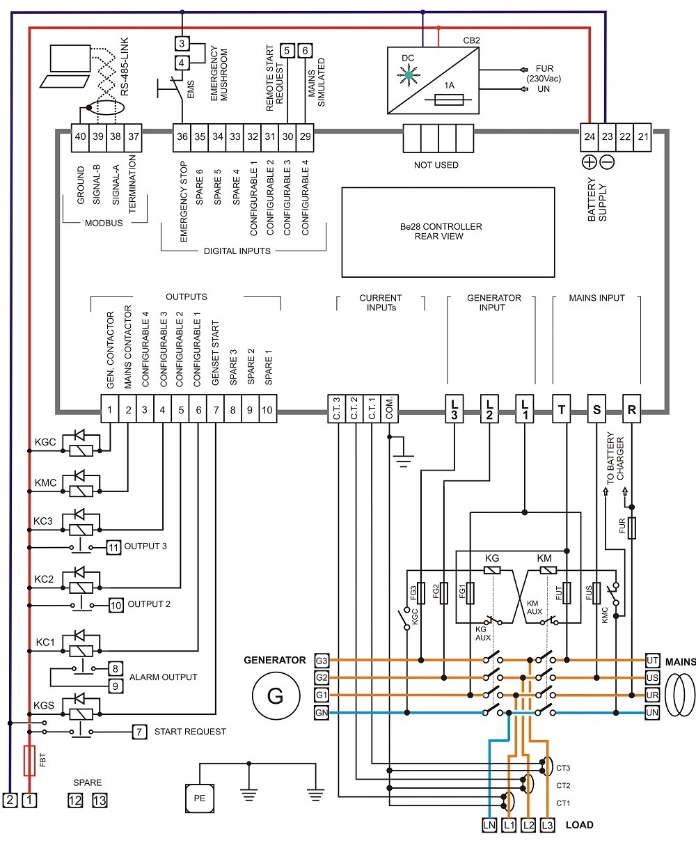
Ats panel wiring diagram. Wellborn variety of ats wiring diagram for standby generator. It is about two electrically controlled circuit breakers. When there is a power failure on mains 1 the pfr will open. The idea of the system is simple. Load ats the overload prevention control board is designed to prevent an overload on the generator when it is supplying the customer loads see figure 12. Ats control wiring diagram wiring diagram is a simplified adequate pictorial representation of an electrical circuit.
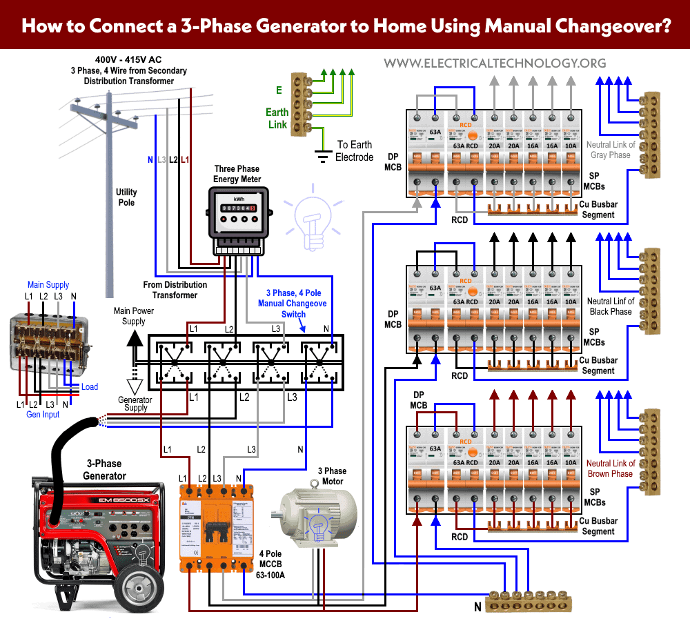
A wiring diagram is a simplified conventional photographic depiction of an electric circuit. A smart way to build an automatic transfer switch is by using two contactors together with an ats controller. Gas valve relay panels and controls. Typical automatic transfer switch diagrams technical information. Up to six loads can be managed by the opcb. Panel voltage selectable transformer breaker neutral ground bond control panel for more information visit.
Testing diesel gen sets to iso8528. A distribution board also known as panelboard breaker panel or electric panel is a component of an electricity supply system that divides an electrical power feed into subsidiary circuits while providing a protective fuse or circuit breaker for each circuit in a common enclosure. A wiring diagram is a simplified conventional photographic depiction of an electric circuit. The ats is connected to utility mains source the ats is connected to utility mains source 1 and the generator source 2 with utility mains as the preferred source. Typical service entrance open transition ats. September 11 2018 by larry a.
Load bank series numbers explained. May 2018 om manual for 600 1000a 480 vac 3 position open service entrance contactor based transfer switch figure 3. Breaker contactor or motorised switch socomec diagram. Motorised switch cl ncl g q1 q2 ats automatic transfer switch protection arent shown on the following schemes summary. The contactors are not allowed to close simultaneously but only one at a time. 300 mcm 6 str line 250 mcm 6 str load ats the conductor tightening torque is 375 in lbs.
In this video you will find out how to use phase failure relay in simple auto changeover application. It shows the components of the circuit as simplified shapes and the capability and signal contacts amid the devices. Asco 7000 series product wiring diagrams. Ats transformer cl ncl g q1 q2 ats genset cl ncl g q1 q2 ats critical load cl ncl g q1 q2 ats non critical load cl ncl g q1 q2 ats standard diagram. Monitoring engine start signals.
Gallery of Ats Panel Wiring Diagram