This video explains how the ballast resistor works. A resistor that has the property of increasing in resistance as current flowing through it increases and decreasing in resistance as current decreases.

5d9fa Ford Pinto Wiring Diagram Ballast Resistor Wiring Library
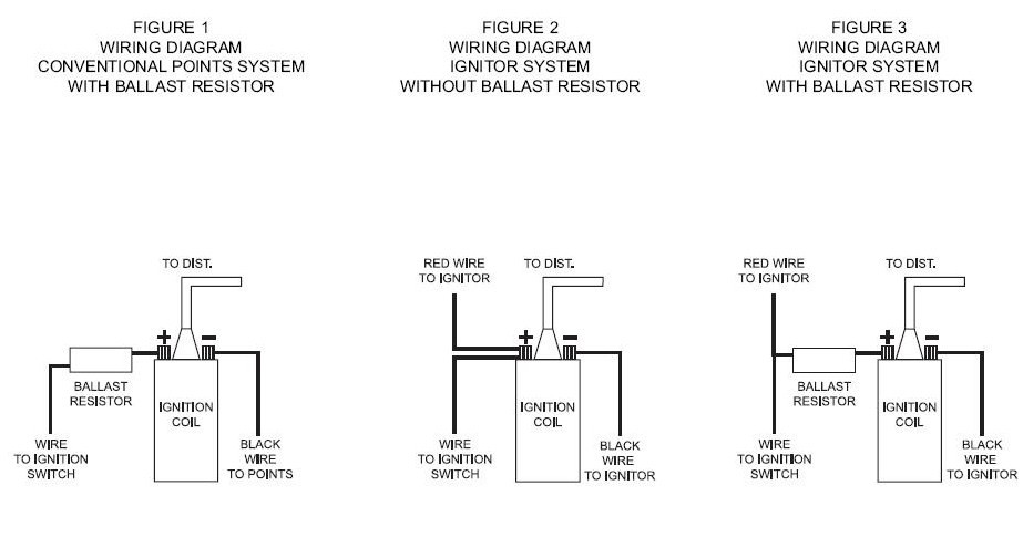
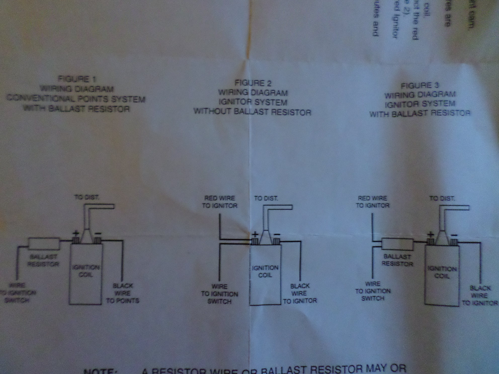
Ballast resistor wiring diagram. Start is only hot 12v dc during cranking and run is hot 12v dc from the moment you turn the key on through crank and after crank. No matter what wattage resistor you have it will see the same power. If its underrated then it will burn up. Well check on this. A ballast resistor is a resistor inserted into a circuit to compensate for different changes. Connect the wire to the unused terminal of the ballast resistor and to the previously identified terminal of the coil.
The ohm is what determines how much power the resistor will see through it. Put a 14 watt 6 ohm resistor across your battery and watch it burn up. Cut a piece of wire long enough to reach from the other terminal of the ballast resistor to the bat or b terminal of the coil. The following diagram shows the 5 pin box with dual ballast resistor. Strip 12 inch of insulation from each end of this wire and crimp a connector onto each end. Some brands utilized a resistor in the coil or a resistor wire hidden in the wiring from the ignition switch but mopar put their resistor or ballast resistor on the firewall or inner fender.
Others might give a different answer to the question what is a ballast resistor like this. Pat conners wrote that wires 2 and 3 should go where 4 and 5 are and vice versa. It shows the components of the circuit as streamlined shapes as well as the power and also signal connections between the gadgets. Variety of 2 lamp t8 ballast wiring diagram. The wattage of a resistor is how much power it can handle. Mopar ballast resistor wiring diagram basic electronics wiring diagram i am planning to replace the distributor with a mallory unilite pointless distributor the instructions emphasize the necessity of either a ballast resistor or a loom resistance wire between the ignition switch and the coil.
A wiring diagram is a streamlined standard pictorial representation of an electric circuit. For additional how to tutorials visit our website. These are very different.
Gallery of Ballast Resistor Wiring Diagram