The sensorless bldc motor reference design code may be used as a starting point for your own code development. Electric bike controller wiring diagram in addition electric motor.

Bldc Motor Control Algorithms Renesas Electronics
Bldc motor controller wiring diagram. Figure 1 is a simplified illustration of bldc motor con struction. By plug i mean the diagram that describes what each of the wires coming out. It shows the elements of the circuit as simplified forms as well as the power as well as signal connections between the gadgets. Electrical energy is converted to mechanical energy by the magnetic attractive forces between the permanent magnet rotor and a rotating magnetic field induced in the wound stator poles. Assortment of bldc motor controller wiring diagram. Unfortunately this one hasnt come with any wiring diagram.
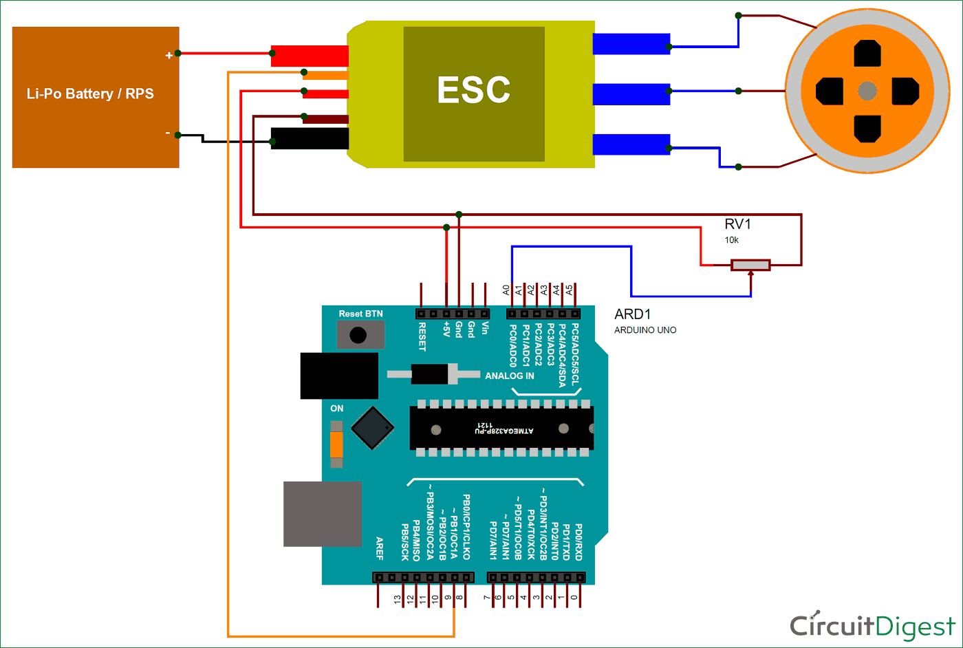
Hook up procedure for groschopp bldc motors locate groschopp drawing as 190 motor connection diagram brushless dc motor. Connect the bldc motor and usb cable if you have not done so already. Collection of bldc motor controller wiring diagram. A wiring diagram is a streamlined standard pictorial representation of an electric circuit. 28 best brushless dc motor images on pinterest. Return to the correct wiring diagram and connect the sensors to terminals s3 s2 and s1 of p1.
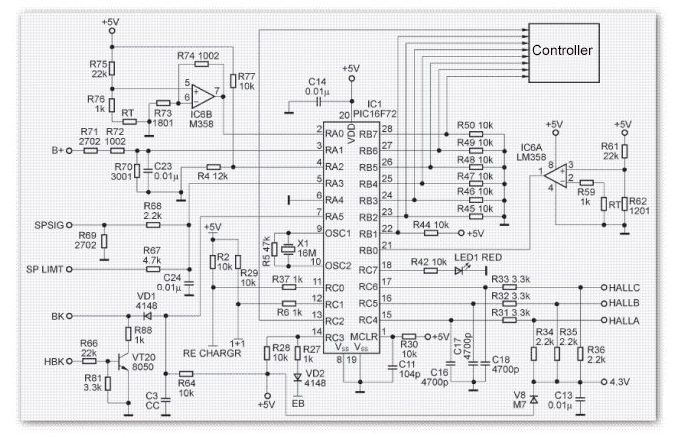
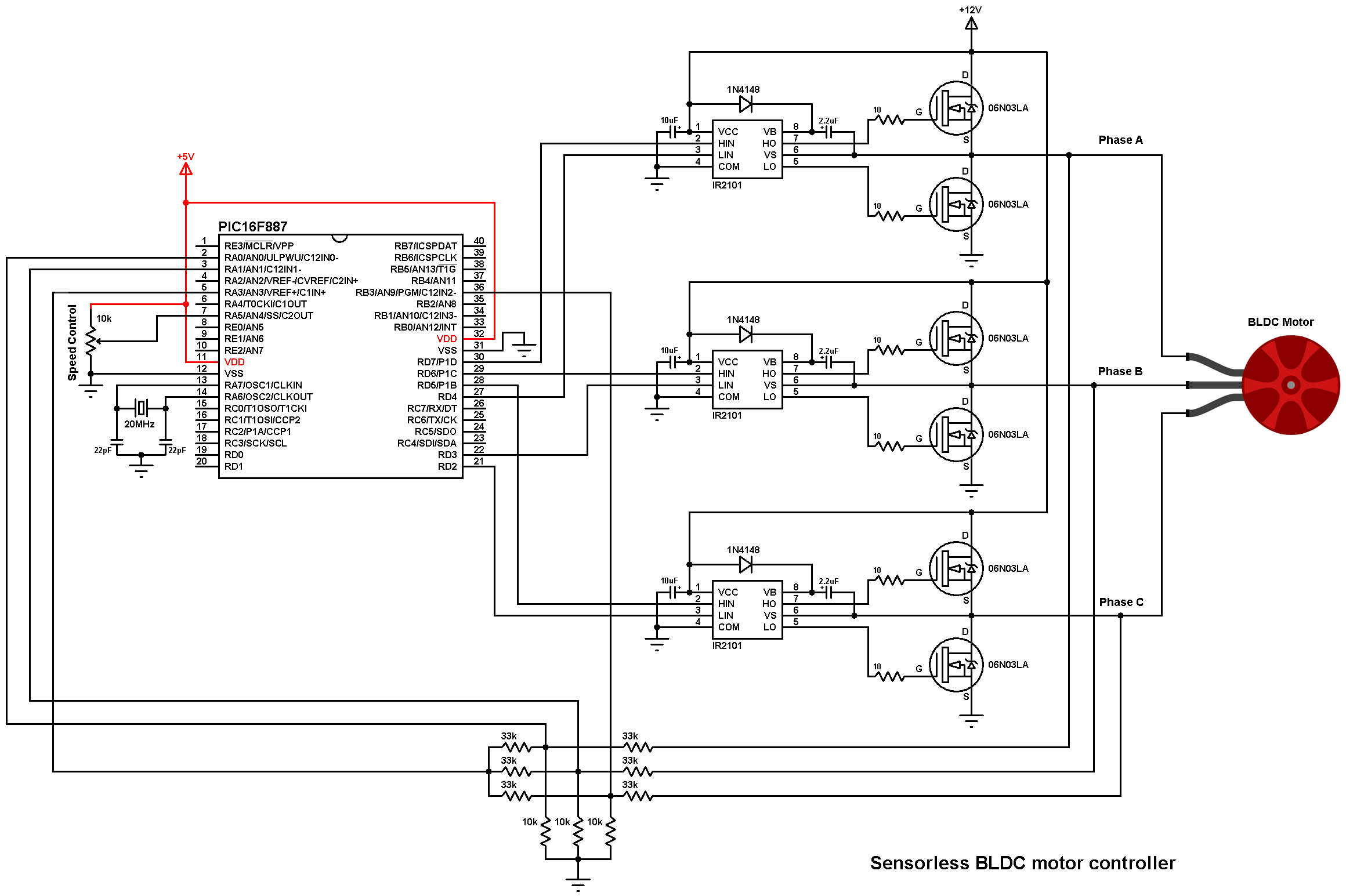
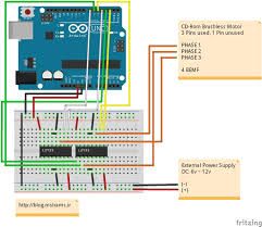
Brushless motor controller schematic the wiring diagram on the opposite hand is particularly beneficial to an outside electrician sometimes wiring diagram may also refer to the architectural wiring program the simplest approach to read a home wiring diagram is to begin at the source or the major power supply. Refer to table 1 bldc motor wiring diagram on page 2 for the bldc motor connections. How to mechatronics 666198 views. How brushless motor and esc work and how to control them using arduino duration. A wiring diagram is a streamlined traditional photographic representation of an electric circuit. Sensored brushless dc bldc motor control with pic16f877a.
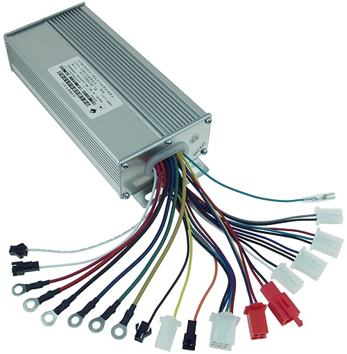
Ebike brushless motor controller identification of wires. Brushless motor controller schematic wiring diagram database. Bldc motor control firmware using the silicon laboratories c8051f310 mcu. The 48v w brushless dc tricycle motor main specification. A brushless motor is constructed with a per manent magnet rotor and wire wound stator poles. It shows the parts of the circuit as simplified forms and the power and also signal links in between the tools.
Bldc motor controller wiring diagram gallery 2018 24v36v48v 250w350w bldc motor speed controller 6 mosfet dual. The diagrams in as 190 show the sequencing of the hall sensor outputs as related to the motor phases.
Gallery of Bldc Motor Controller Wiring Diagram