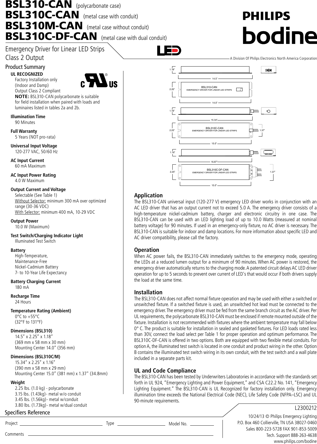
A patented circuit delays ac led driver operation for up to 5 seconds. Listed to ul924 and tested to csa 222 no.
B100 Wiring Diagram Get Bodine B100 Wiring Diagram Download
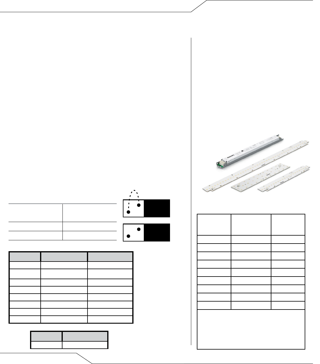
Bodine bsl310 wiring diagram. After installation is complete supply ac power to the emergency driver and join the converter. 2x wires z as per the bsl wiring diagram. To verify that this is the correct wiring diagram for your bodine product please check for the connection diagram reference number in the specifications table on the applicable itemmodel page. By admin october 12 2018. Connect the bsl red to. The bsl310 operates an led load of up to 100 w at nominal battery voltage for a minimum of 90 minutes.
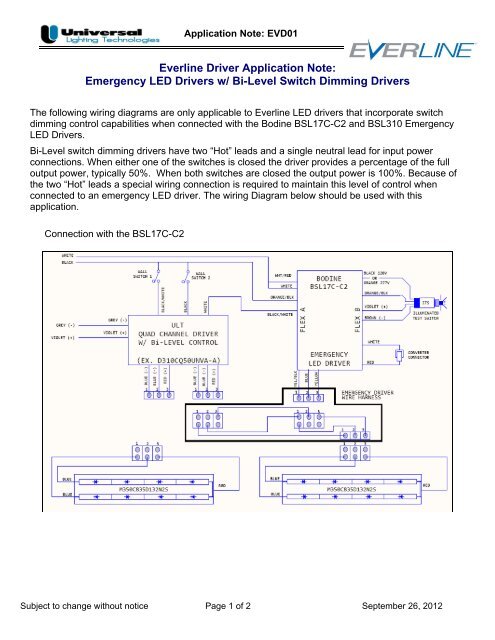
After installation is complete supply ac power to the emergency driver and join the converter. Connection diagram for 230460vac 9 wire reversible 3 phase gearmotors and motors 07410012. Wiring or electrical components during kit installation. The bsl310 operates an led load of up to 100 w at nominal battery voltage for a minimum of 90 minutes. Noteake sure the. Step 3 wiring the emergency driver select the appropriate wiring diagram to connect the emergency driver to the ac driver and led load.
141 for field or factory installation indoor and damp. Make sure all connections are in accordance with the national electrical code and any local regulations. 2 wire input helps reduce wiring errors compatible with a variety of led strip manufacturers compatible with ac drivers and led loads rated for class 2 rohs compliant dimensions 1534 x 225 x 116 mounting center 150 led bsl310m 150 225 116 137 1534. Consult the factory for other wiring diagrams. Make sure all connections are in accordance with the national electrical code and any local regulations. Bsl310 wiring diagram nov 1 philips bodine bsl emergency led driver for evokit g2.
Philips bodine bsl310 wiring diagram. Step 3 wiring the emergency driver select the appropriate wiring diagram to connect the emergency driver to the ac driver and led load. Specification emergency lighting shall be provided by using a led fixture equipped with a philips bodine bsl310 universal input 120 277 v emergency driver. Click download pdf to view this wiring diagram. To prevent high voltage from being present on yellow yellow black output leads prior to installation converter connector must be open. Specification emergency lighting shall be provided by using a led fixture equipped with a philips bodine bsl310 universal input 120 277 v emergency driver.
A patented circuit delays ac led driver operation. Wiring diagram electrical wires cable schematic philips bsl310 emergency ballast by philips bodine 13522d6 bodine b50st emergency ballast wiring diagram library emergency led drivers w universal lighting technologies. Do not join converter connector until installation is complete and ac power is supplied to the emergency driver. Wiring diagrams 2 warning.
Gallery of Bodine Bsl310 Wiring Diagram