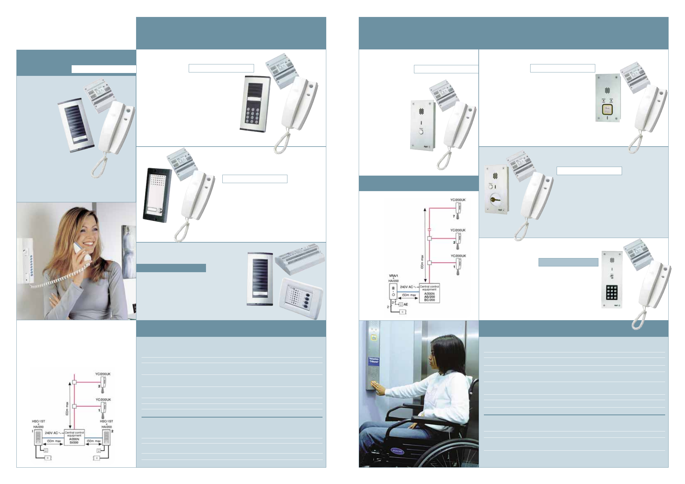
4 cores 0 05mmsq for 100m t core o o5uusq per. As we are a major distributor of bpt products from their access control systems to audio intercoms.
1 8 Maf Wiring Diagram Help Miata Turbo Forum Boost Cars
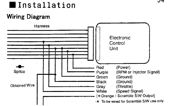
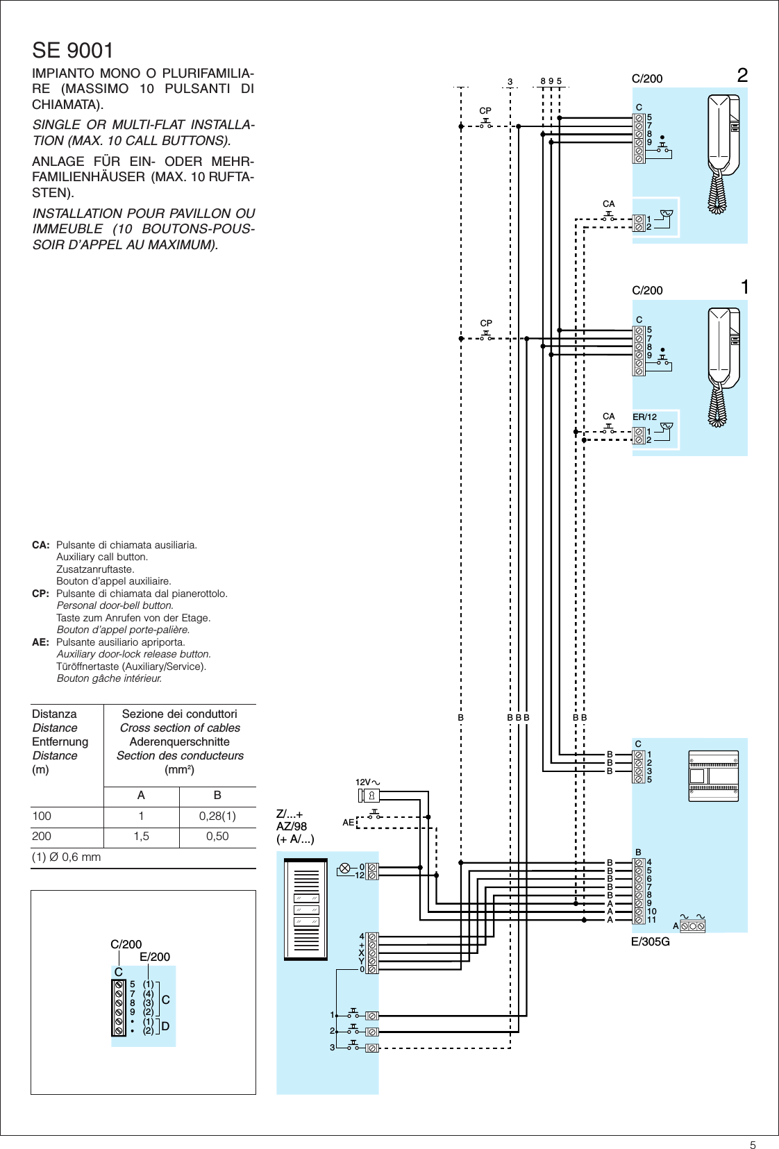
Bpt 200 wiring diagram. Bpt yc 200 wiring diagram. Here you will find all the wiring diagrams on the site that we have for bpt of which there are many. Wiring diagrams for bpt products. The bpt yc handset is compatible with. Bticino 2 wire audio kit duration. Bpi cni as v12ccpj.
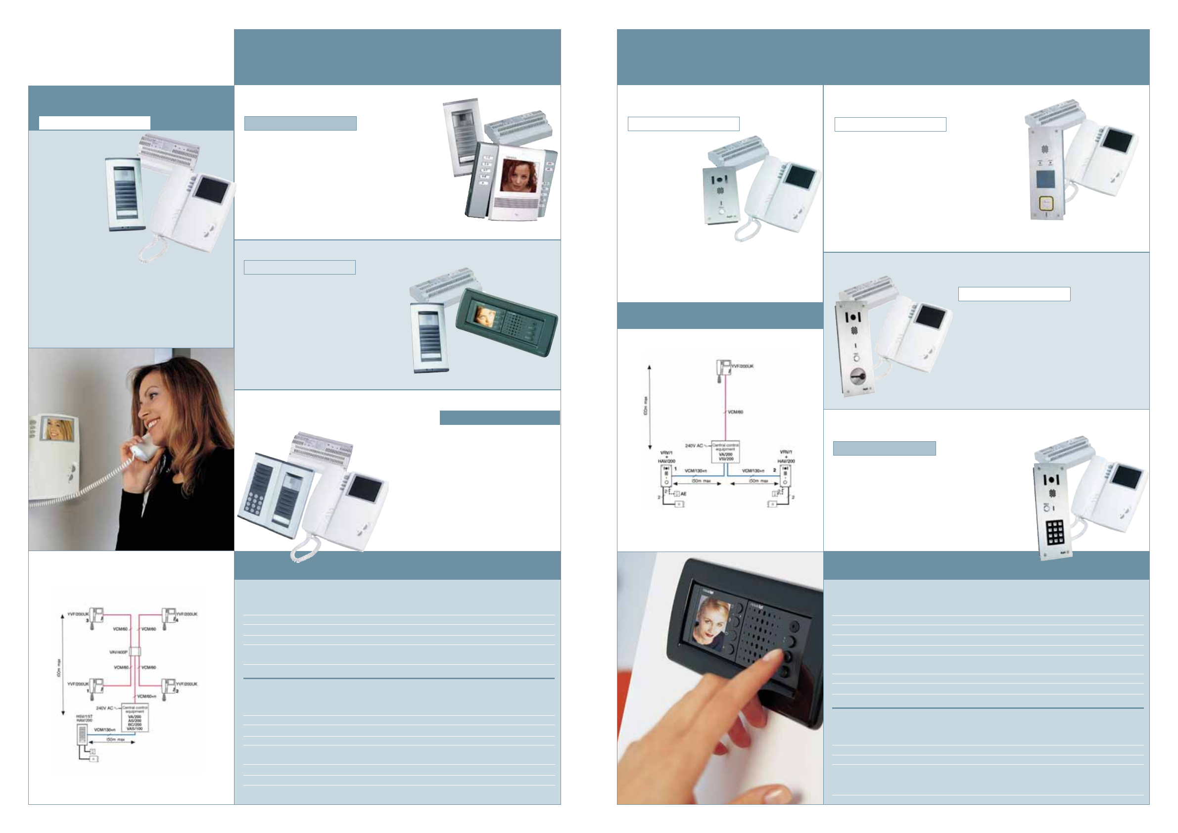
Wiring diagram bpt audio with 2 entrance panels and keypads. Comelit vox 2000 audio wiring diagram. Engineers area staff only bticino lt terraneo engineers area staff only cdvi. Digi code keypad programming and wiring. By continuing to navigate you authorize the use of cookies on this site. 6 cores 0 05mmsq 2 cores o iommsq for 150m call unes to yc200s note.
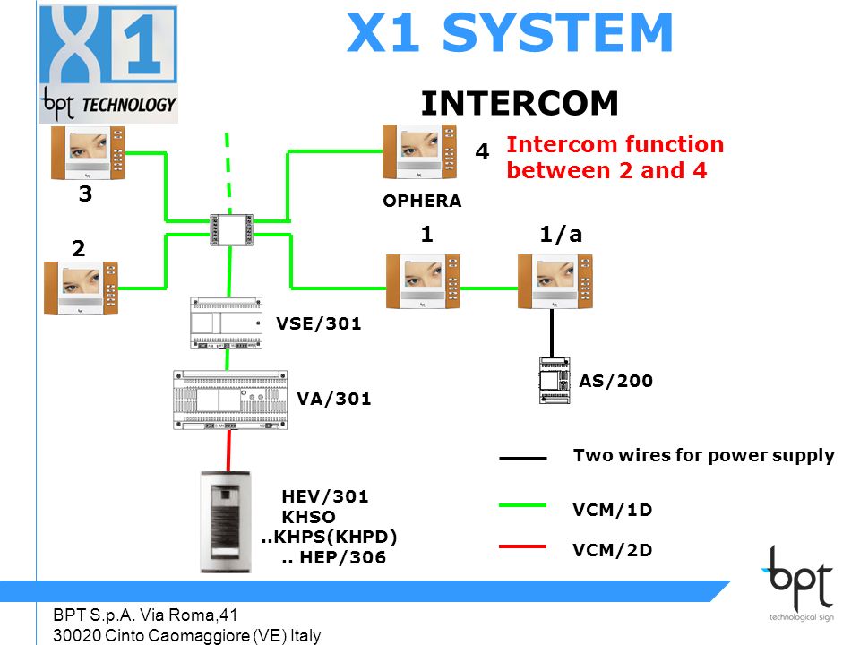
Unsubscribe from golf wagen. Relay unit 4 pages. Bpt wiring diagrams for system 200 products. Wiring diagram bpt audio 1 way. Bpt quick start guide x1 thangram bvkit. Wiring diagram bpt 1 way audio.
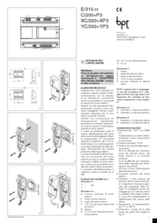
01012019 01012019 6 comments on bpt yc 200 wiring diagram. Xc200 cd200 c200 xc200 cd200 xv200 cd200 calls from the porters switchboard function of each terminal and wire fig. Bpt quick start guide x1 thangram evkit. We continue to expand all our downloads so you can keep checking back here for updates. Bpt audio 2 entrance. 1 the connection must be made to terminal n2 before note type b can terminal block 10.
Simple connect bpt audio system 200 golf wagen. Bpt quick start programming. Intercom system bpt hac200 installation diagrams 8 pages relays bpt vls101 installation instructions. 3 3 8. The use 12 241 9200 for 150m couuon unes to yc200s. This site uses cookies to monitor and personalize the users browsing experience.
For any diagrams not shown or special system designs please contact our office on yca. View and download bpt agata c 200 installation manual online. We are always adding new products and therefore new wiring diagrams so keep checking back here for new ones. This drawing indicates and assumes a minimum of 05mm csa per core. View our complete range of system 200 wiring diagrams. This drawing indicates and assumes the use of a minimum of mm csa per core.
3 disconnect wires on pin 11 and pin 12 this is to ensure that a wirel. Agata c 200 intercom system pdf manual download. Agata cb 200 targha 200.
Gallery of Bpt 200 Wiring Diagram