Simply solder them to your flight controller accordingly to the labels. This vehicle is designed not only to travel 1 location to another but also to carry heavy loads.
Doorbell Wiring
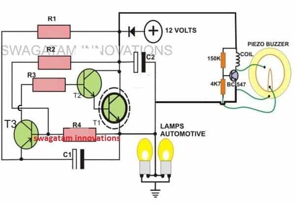
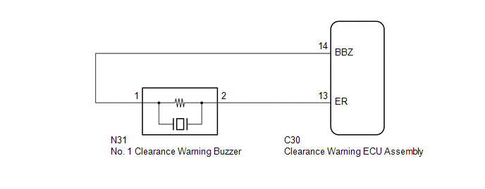
Buzzer wiring diagram. How to connect the vtx. All information published in the vehicle diagram pages is gathered from sources which are thought to be reliable and accurate but we advise everyone check and verify our information by testing with a computer friendly test light to ensure proper connections are made. Flightone wiring diagrams collection of flightone product wiring diagrams. You can use any coil from 1mh to 10mh or more or even no measured value at all. The current flow diagram can tell you everything that you need to know right away. Fire alarm systems are wired in industrial factories offices public buildings and nowadays even in homes.
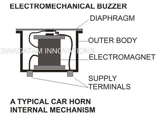
A buzzer is a small yet efficient component to add sound features to our projectsystem. 0 march 31 2020 dji to revoltosd wiring diagram. Connect a real pit vtx pit switch. Electrial diagrams 924 1978 legend current flow symbols part 1 page 1 page 2 legend part 2 page 1 page 2 legend part 3 page 1 page 2 legend part 4 page 1 page. 1985 porsche 944 fuse box diagram 1985 porsche 944 fuse box map fuse panel layout diagram parts. Sticker to show how awesome device you have to protect your gear.
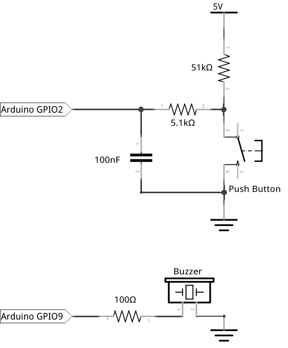
Connecting rgb or ws2811 leds. 3x 10cm silicon wire black red white 2x spare heat shrink. In case of emergency the sounders will operate to warn the people around to evocative via general or emergency exit. I used a 40 turn coil on a small ferrite toroid in the final design. Different types of fire alarm system such as conventional addressable intelligent and smart wireless designs are used for the same purpose ie. The buzzer connects to your flight controller via 3 cables.
This report will be talking trailer indicator buzzer wiring diagramwhat are the advantages of knowing these knowledge. With many modern cars it is best to take power from a source such as the bus bars at the back of the fusebox. How to connect receivers. Towbar buzzer wiring diagram. The blue wire is connected to feedbackf terminal red wire to the main m terminal and the black wire to the piezo elements groundg platethe inductor coils value and shape is not crucial. 5v to your buzzer pad or 5v bec output.
How to connect the camera. 15 articles megabolt extreme. Trailer indicator buzzer wiring diagram trailer indicator buzzer wiring diagram people today understand that trailer is a car comprised of quite complicated mechanics. It is very small and compact 2 pin structure hence can be easily used on breadboard perf board and even on pcbs which makes this a widely used component in most electronic applications. This is either with a flasher unit or with a frequency control unit incorporated into the central electrics.
Gallery of Buzzer Wiring Diagram