Cat 5 wiring diagram crossover cable diagram. Click to find view print and more.
Ethernet Wiring Practical Networking Net
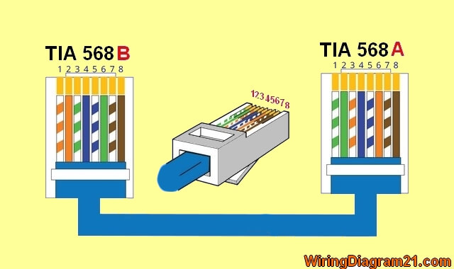
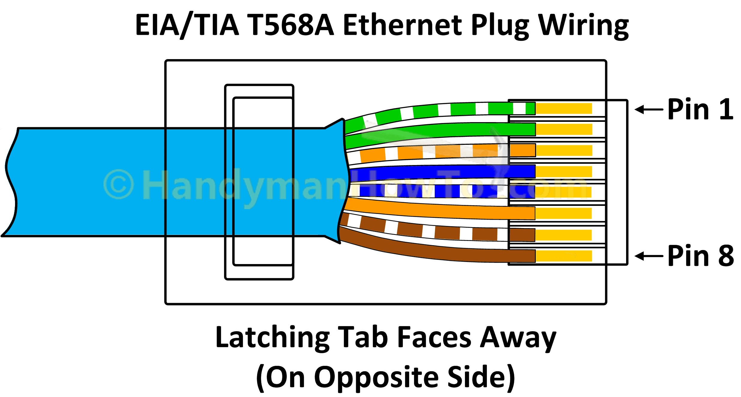
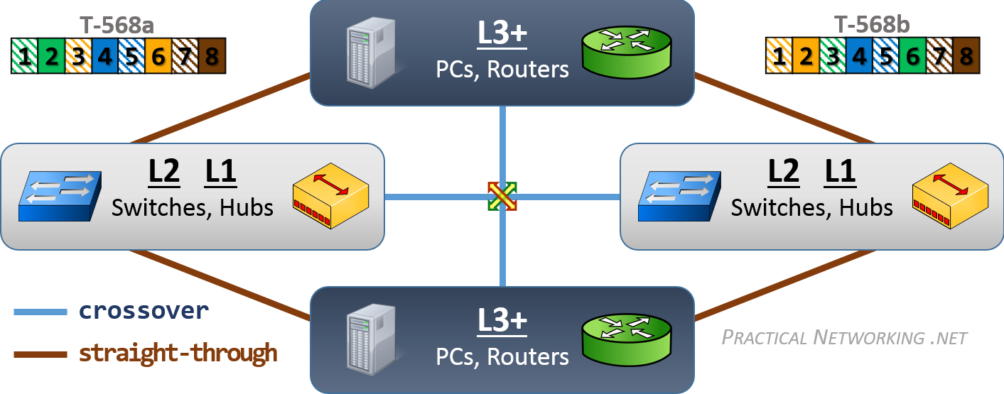
Cable wiring diagram. Wiring diagram for npn and pnp 4 wire sensors with the d2 16nd3 2. Jacks are designed to work only with solid ethernet cable. Gs 1 serial port terminal adapters. Rj45 pinout diagram shows wiring for standard t568b t568a and crossover cable. However for the crossover wiring method the rj45 pinouts on each end of the cat5e are different. Click to check the right one for you or print as reference.
Please note that these instructions are the same for cat 6 cable and and other type of 4 twisted pair network cable. Wiring diagram for npn and pnp 2 wire sensors with the d2 16nd3 2. Ethernet cable color coding diagram for. Most jacks come labeled with color coded wiring diagrams for either t568a t568b or both. The complete ethernet pinout cable wiring reference with wiring step by step guide. This cat5 wiring diagram and crossover cable diagram will teach an installer how to correctly assemble a cat 5 cable with rj45 connectors for regular network cables as well as crossover cables.
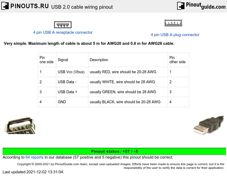
If you are an existing customer and have questions about your wiring or connection please call 780 450 6787 email. Modular connector plug and jack pin out ethernet cable pin outs. Youll love our internet and hosting services. Here is a wiring diagram and pin out. Wiring diagram for ac inductive and photo type sensors with the d2 16na. Make sure you end up with the correct one.
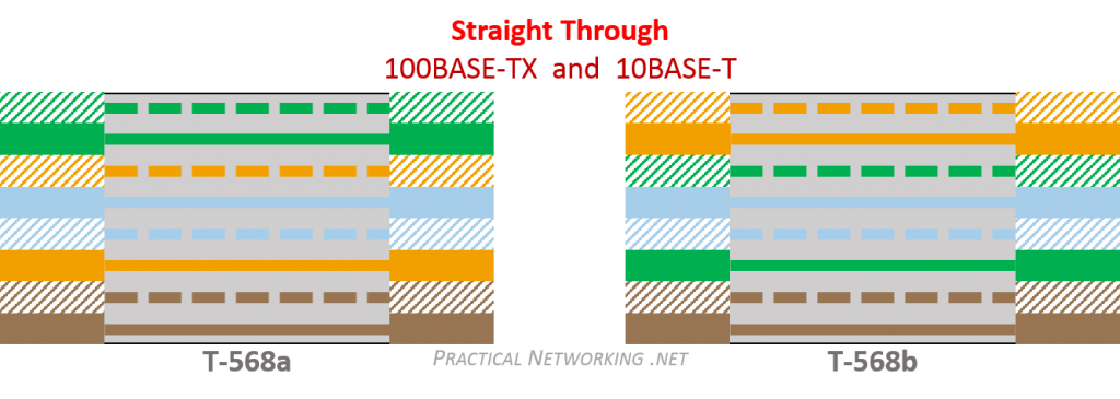
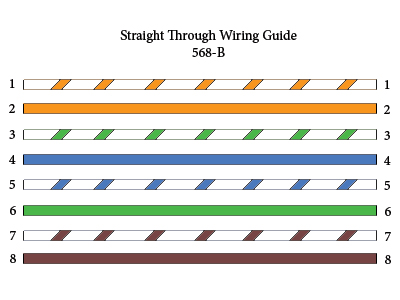
The choice is one of requirements and preference. The following picture shows the wiring diagram of the two standards. Remember the rj45 wiring order. Wiring diagram for npn and pnp 3 wire sensors with the d2 16nd3 2. When you are doing the straight through wiring the cable pinout on the two ends of the cat5e cable should be the same.
Gallery of Cable Wiring Diagram