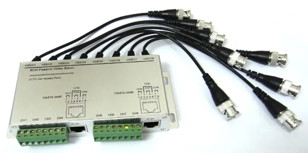
For baluns that also supply power to cameras one of the twisted pairs from the cat5 cable is used for video and 2 pairs are used for power. A wiring diagram is a streamlined standard photographic representation of an electrical circuit.

Rj11 Wiring Diagram Using Cat5 Wiring Diagram And Schematic
Cctv cat5 wiring diagram. Pro series cameras and value series cameras have differently colored wires so each camera has its own wiring diagram. Collection of cctv camera wiring diagram. February 9 2020 by larry a. It reveals the elements of the circuit as simplified shapes and also the power as well as signal links between the tools. Today there are a lot of options when it comes to choosing a quality cctv security system. A wiring diagram is a streamlined traditional pictorial depiction of an electric circuit.
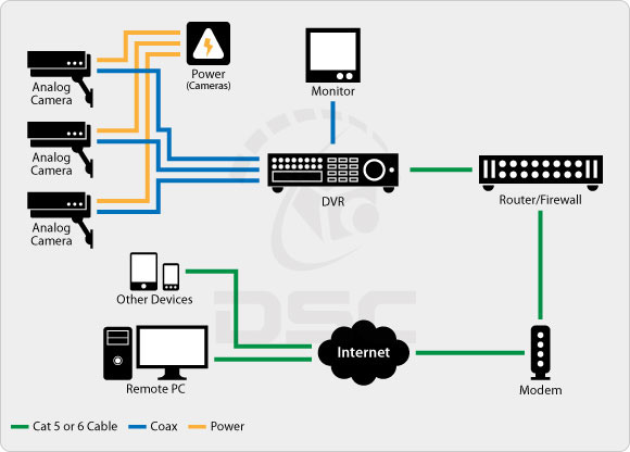
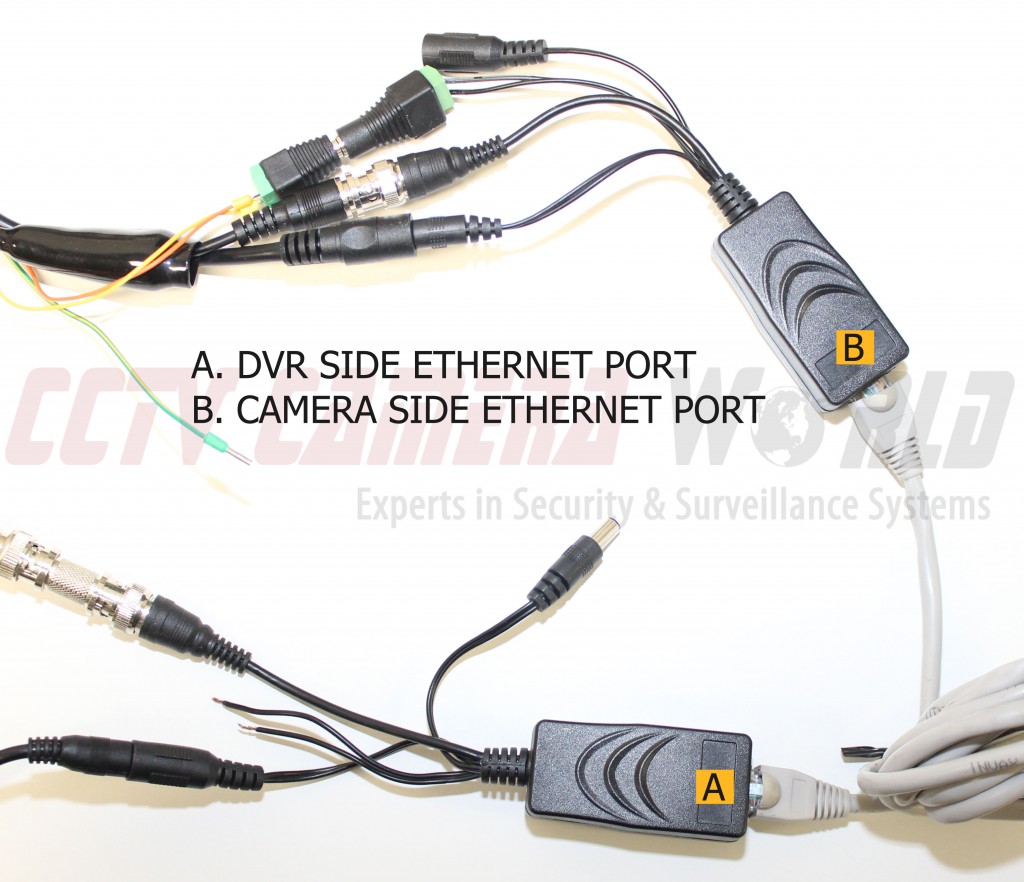
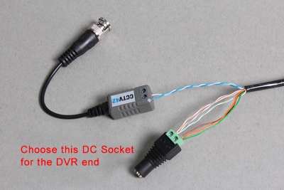
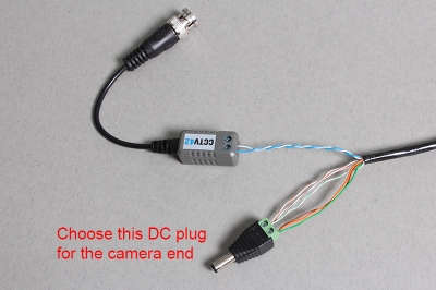
Using cat5 cable to wire cctv cameras in recent years the invention of the video balun has meant cat5e cable can be used to connect cctv cameras to cctv dvr recorders. One thing all of these options have in common is you will probably have to run some sort wire to the cameras. This cat5 wiring diagram and crossover cable diagram will teach an installer how to correctly assemble a cat 5 cable with rj45 connectors for regularfeb 20 this shows how baluns are used in conjunction with cat5 cable to connect a cctv camera to a dvr recorder. Wellborn assortment of cat5 cctv wiring diagram. The reason why the green cable is separated by the blue set is that it allows for longer cable runs up to 100m. Cat5 cctv wiring diagram building electrical wiring diagrams show the approximate locations and interconnections of receptacles illumination and irreversible electrical solutions in a building.
Cctv installation and wiring options. Please see the below wiring diagram which illustrates this. Interconnecting cable routes may be shown roughly where particular receptacles or components must be on an usual circuit. Video baluns with power. The hikvision cameras dont use the standard cat5cat5ecat6 color coded wiring. Cat5 straight diagram this diagram is used for straight through cables also called patch cables and theyre the standard ethernet cable used when youre connecting a device to a router switch or hub.
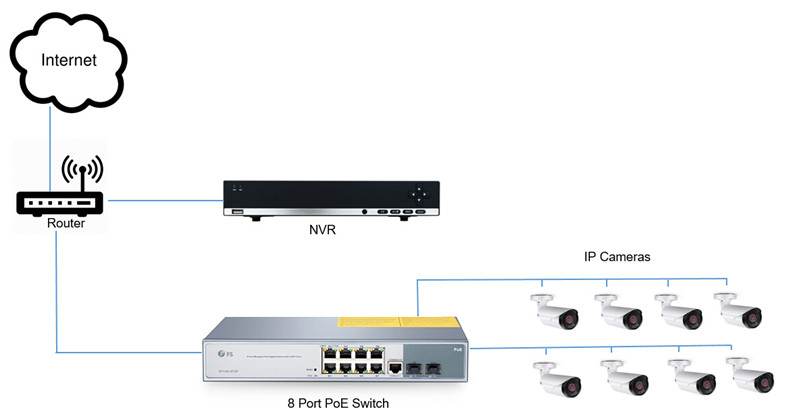
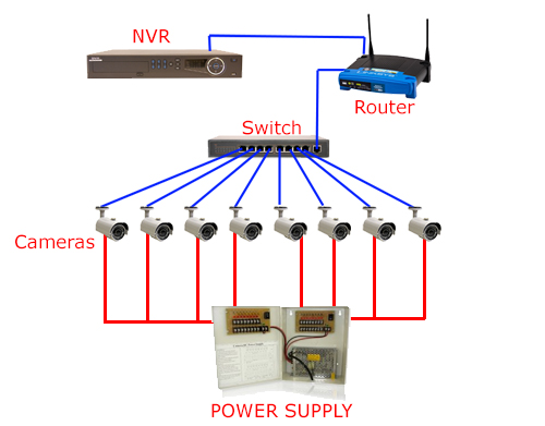
You may decide to go with a traditional analog system hd sdi hd cvi or even an ip network based security products. It shows the elements of the circuit as simplified forms and also the power and also signal links between the gadgets. Video baluns with power support running low voltage power to cctv cameras in addition to transmitting the video signal. Cat5 network wire diagram. This cat5 wiring diagram and crossover cable diagram will teach an installer how to correctly assemble a cat 5 cable with rj45 connectors for regular network cables as well as crossover cables. Please note that these instructions are the same for cat 6 cable and and other type of 4 twisted pair network cable.
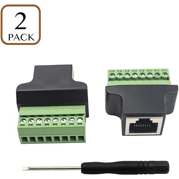
To connect a new connector rj45 jack to the hikvision ip camera refer to the diagrams below. All the connections can be made using only a screwdriver no need for special tools or fiddly components.
Gallery of Cctv Cat5 Wiring Diagram