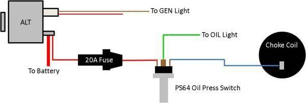
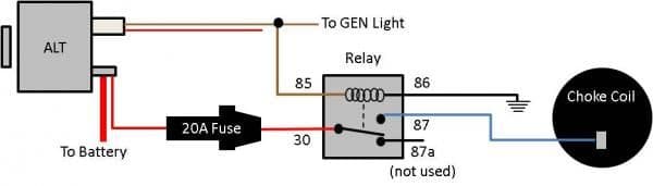
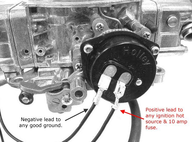
Connect the long wire from the kit to the positive choke cap terminal marked. Walker year model disp.

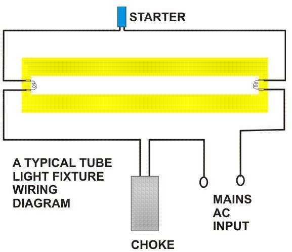
Tube Light Connection Circuit Amp Wiring Diagram Electrical4u
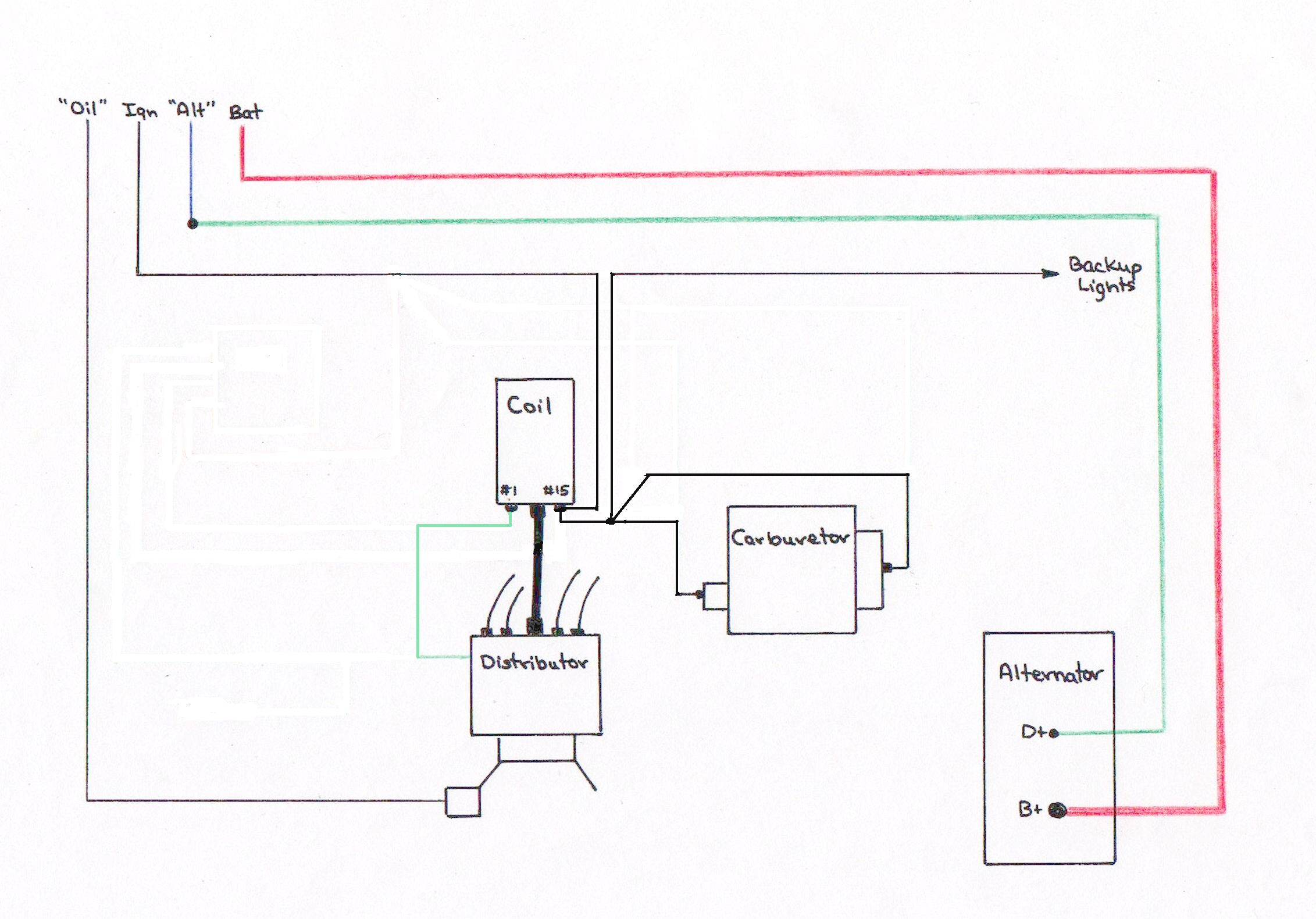
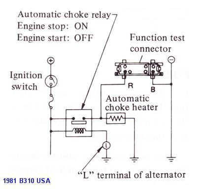
Choke wiring diagram. This eliminated all the problems i had been having with the choke. B b buickuickuick 8 cylinder contd 1984 81 all models 50ly 307 r 4 17066792 17068941 102 1012. One terminal of choke or ballast is connected to port 1 and another terminal is connected to pin 1 of terminal 1. 1984 chevy truck wiring an electric choke of an edelbrock carburetor. Choke thermostats application guide 332 vehicle engine mfg. The white wire is the wiper supply line and the red one is the wire i spliced into it.
Wiring diagram of single tube light installation with electronic ballast. The choke cap should only get voltage when the engine is running. Then i connected the other end of the wire to the plus terminal on the choke assembly. One wire goes on my wiring diagram it shows. Ignitionedelbrock carburetor linkage also carter afb choke diagram along with question throttle rod edelbrock a moreover moreover edelbrock electric choke problems in addition edelbrock exploded view wiring diagrams together with edelbrock power valve diagram. Connect the other end of the wire to a fused ignition activated 12v source.
Ignition feed and one that says. One end of a starter is connected to pin 2 of terminal 1 and another end of the starter is connected to the pin 2 of terminal 2. Wiring diagram electric choke you are welcome to our site this is images about wiring diagram electric choke posted by alice ferreira in diagram category on nov 13 you can also find other images like wiring diagram parts diagram replacement parts electrical diagram repair manuals engine diagram engine scheme wiring harness. Check your voltage source with a voltmeter. For demonstration on adjustment of the edelbrock carburetor i recommend this link http.
Gallery of Choke Wiring Diagram