More designing and 3d printing of parts for the project. The z axis switch is simply screwed into the z axis mount.

End Stop Limit Switch Problems 3 Steps Instructables
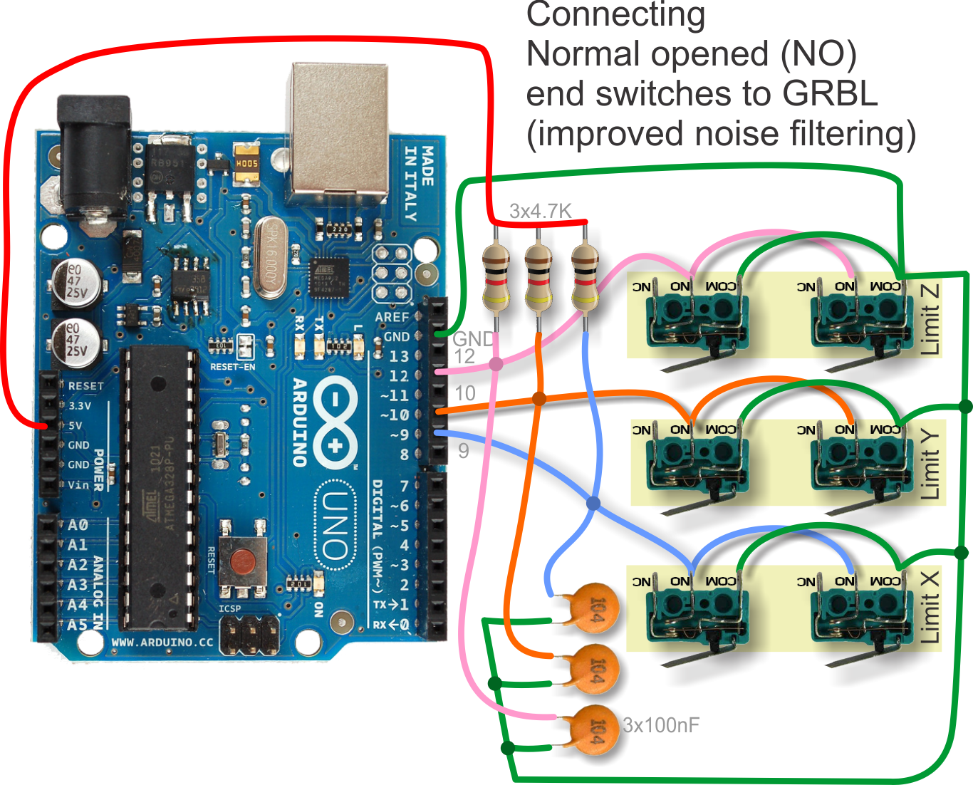
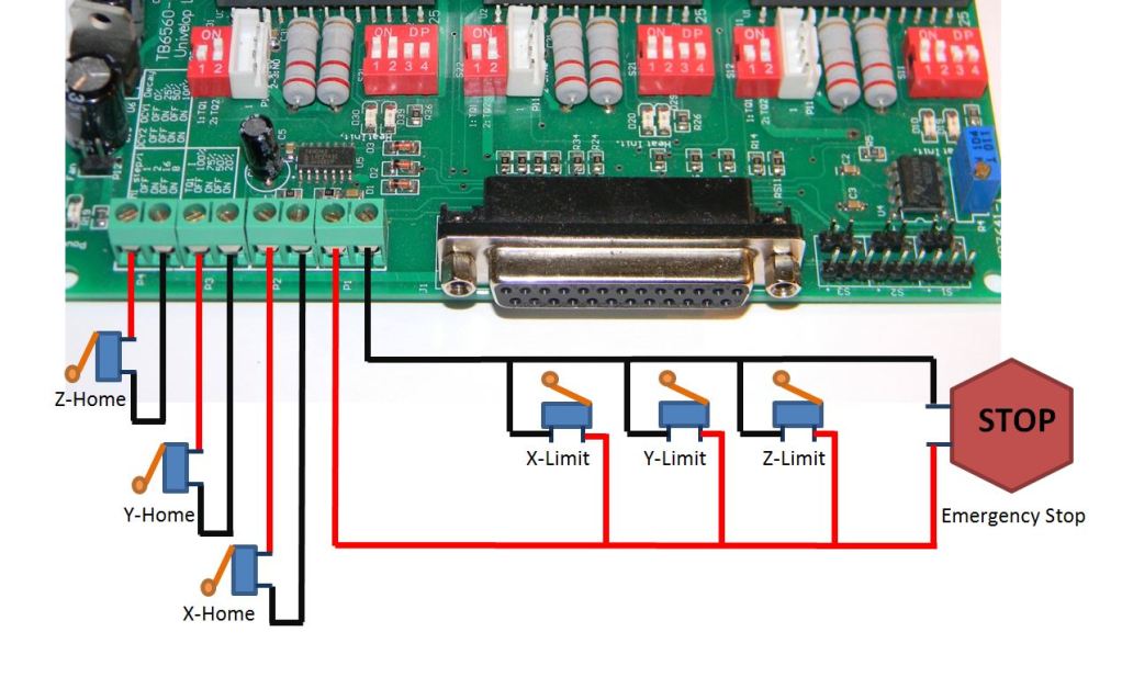
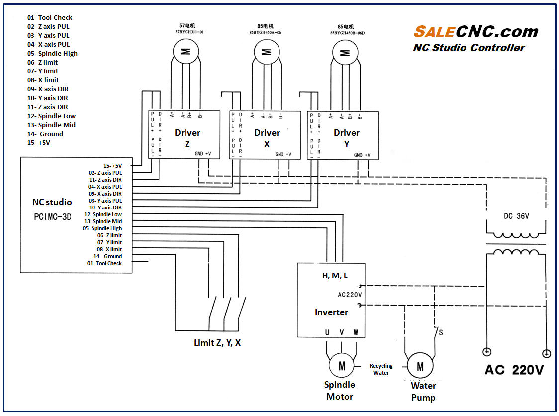
Cnc limit switch wiring diagram. Connect the black and green wires in location as shown in the following images and diagram the red wire is not connected this would be for an led. Make sure all pins are wired through. Solder a red and black wire to the limit switch and add dupont connectors to the other end. Beginners guide to home and limit switch hardware mach3 cnc duration. The location for connecting each switch is shown on the pcb. Therefore each limit switch black 3 pin connector plugs into the header with the green wire to the upper pin and the black wire to the lower pin.
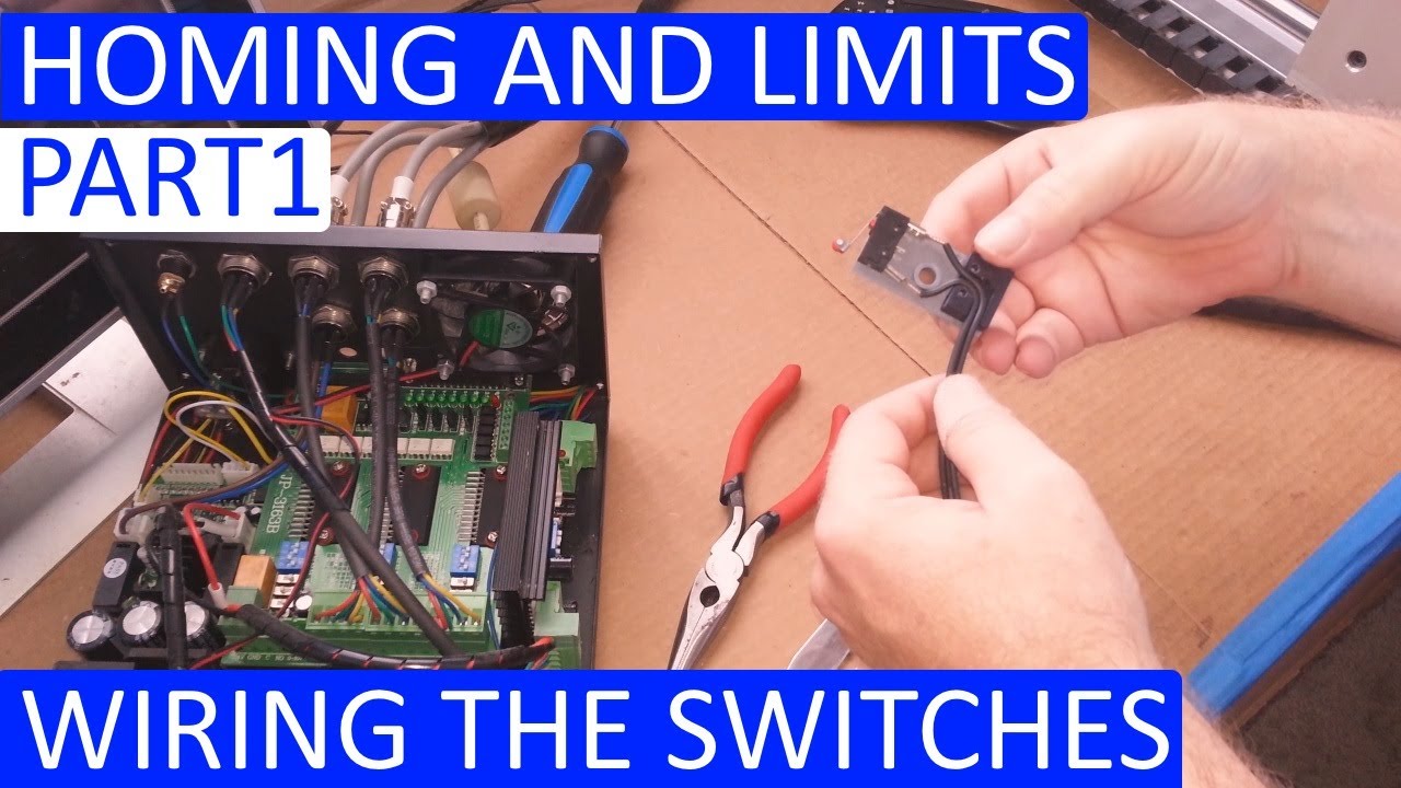
Part 1 of wiring for the home switches. The green wire is the common of the switch and the black is the normally open contact. Wiring harnesses that were supplied with the switches have three wires two of which we are using. Cnc wiring diagram myrobertadams. Beginners guide to home and limit switch hardware mach3 cnc duration. Attaching limit switch wires to the cnc shield.
Plug them into the pcb according to the wiring diagram. Use one of the extra wires we ran through the dragchain in the previous step to connect this limit switch to the main board. What the ends of a parallel port extension cable will look like. Optimise wiring to complete fitting.
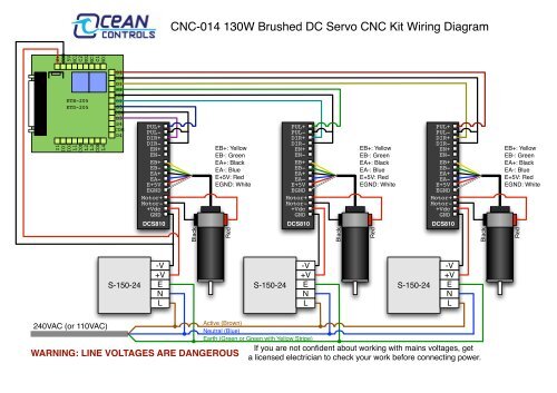
Gallery of Cnc Limit Switch Wiring Diagram