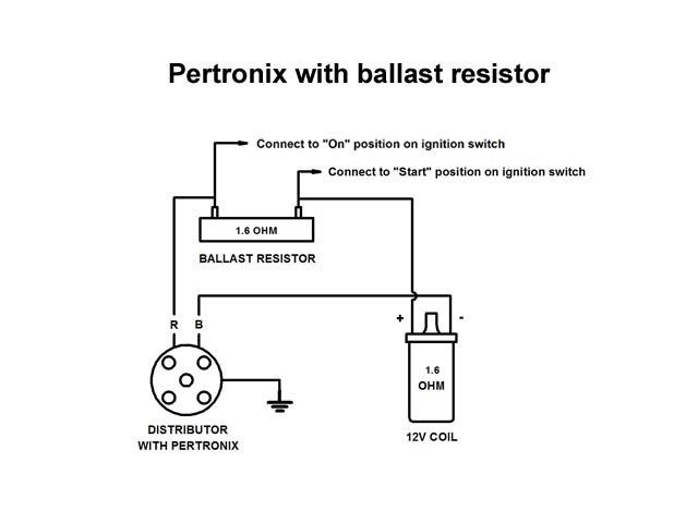
The purpose of an ignition ballast resistor between the ignition switch 12v and the ignition coil positive terminal is to restrict current flow. This is the ignition coil ballast resistor wiring diagram agnitum of a imagine i get via the ignition coil distributor wiring diagram package.

Ballast Resistor Or Not Jeepforum Com
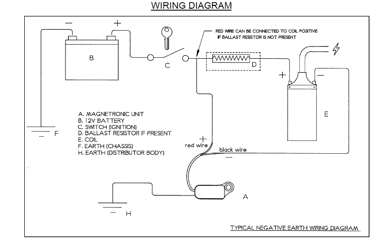
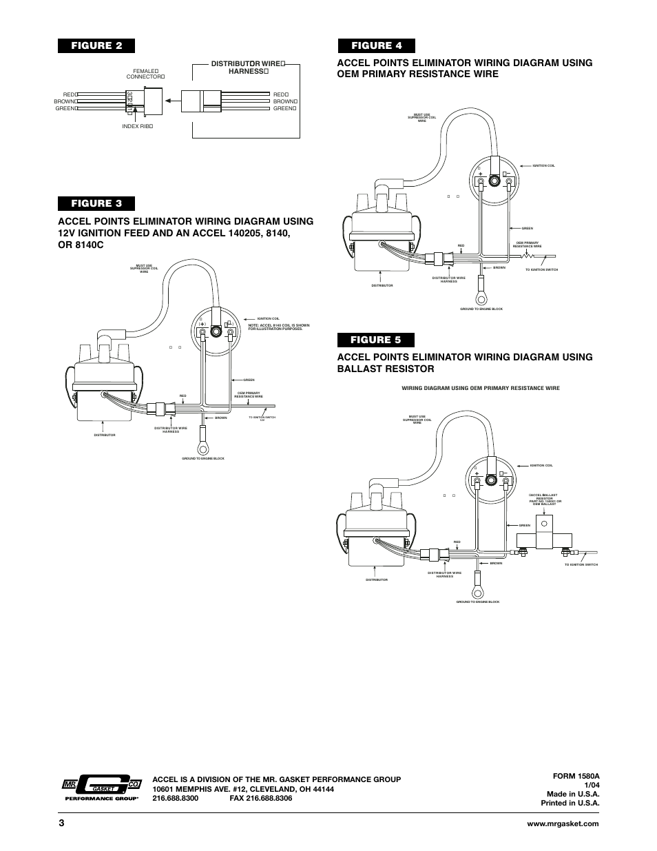
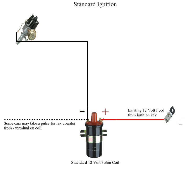
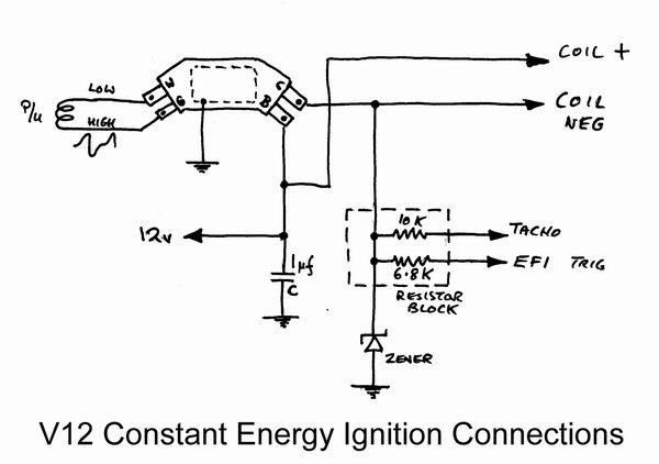
Coil resistor wiring diagram. Diagram attached for wiring of points dizzy and coil with ballast resistor. A resistor that has the property of increasing in resistance as current flowing through it increases and decreasing in resistance as current decreases. Here are a few of the top drawings we get from various sources we wish these photos will certainly be useful to you and ideally really pertinent to exactly what you want concerning the ignition coil distributor wiring diagram is. 800 x 600 px source. This simple system is easy for even the novice mechanic to wire. Please right click on the image and save the photograph.
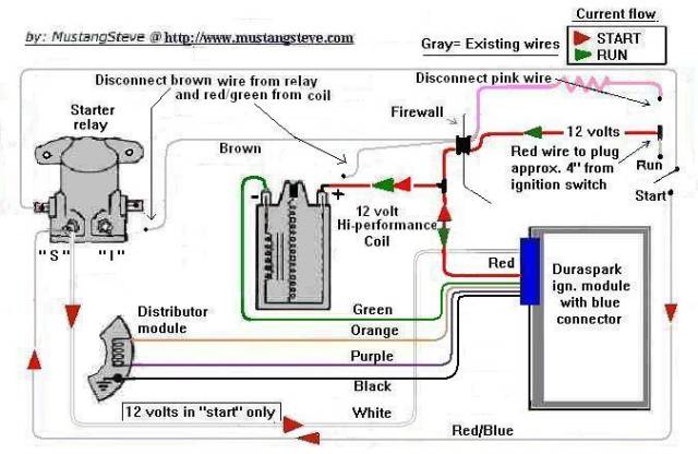
Strip 12 inch of insulation from each end of this wire and crimp a connector onto each end. As a matter of fact a bad diode trio in a conventional alternator can do the same damage. Cut a piece of wire long enough to reach from the other terminal of the ballast resistor to the bat or b terminal of the coil. Connect the wire to the unused terminal of the ballast resistor and to the previously identified terminal of the coil. You can save this graphic file to your own pc. Discussion in 1960 1966 started by ol betsy dec 20 2006.
We also have some more photos connected to ignition coil distributor wiring diagram please see the photo gallery below click one of the. Ignition coil distributor wiring diagram size. Dec 10 2016 automotive wiring diagram resistor to coil connect to distributor wiring diagram for ignition coil. Wiring diagram for ignition coil.
Gallery of Coil Resistor Wiring Diagram