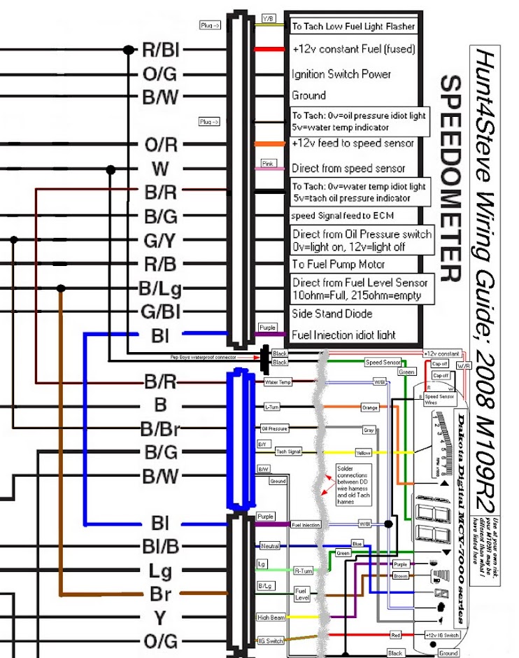
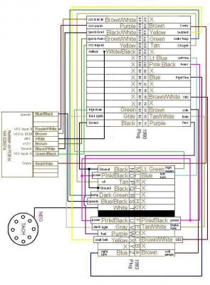
Page 11 whiteblue connects to the adj snd. Sensor red white black blue brown additional ground wire to fuel sensor body or mounting screw.
S13 1jz 2jz Speedometer Write Up Zilvia Net Forums Nissan
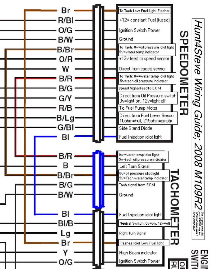
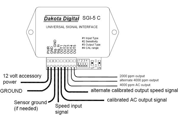
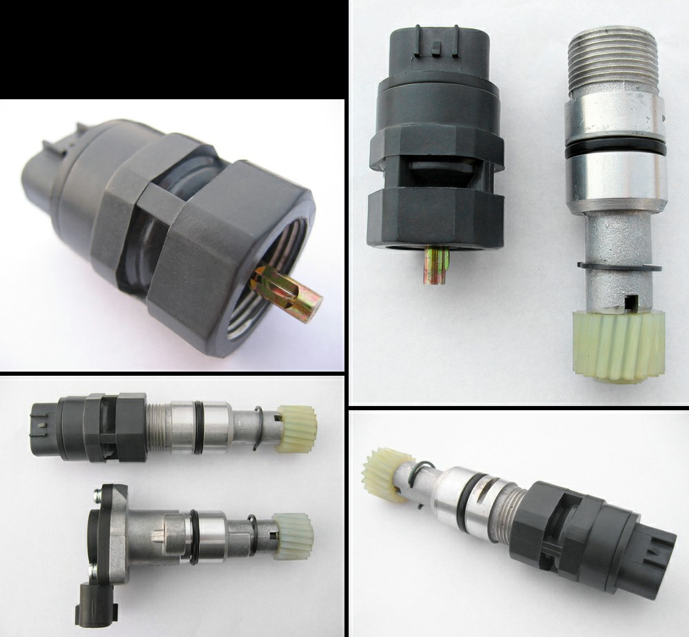
Dakota digital speed sensor wiring diagram. All dakota digital speedometers are gps ready meaning they are prepared for connection with a gps speed sensor such as our gps 50 2 allowing any speedometer to utilize gps technology. Wiring the sensor will generate an ac voltage thats frequency and voltage level will vary with the drive speed. Dakota digital gss unit 1 wire output right turn signal wire optional left turn signal wire high beam wire parking brake switch speed out 2k or 4k ppm connect to tail light circuit led backlights will turn on when termianl has 12v light or buzzer 4 watts or more tail light light or buzzer 4 watts or less relay existing fuel level sensor. Testing either a 2 or 3 wire hall effect speed sensor is a relatively easy task and one that can save you quite a bit of money in the long run. With transmissions having the built in electric sensor a three wire harness adapter connects the transmission speed sensor to the speedometer. Sensor red white black red black additional ground wire to fuel sensor body or mounting screw.
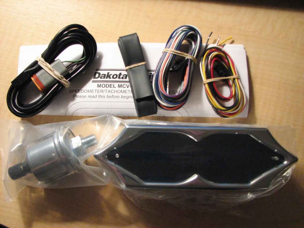
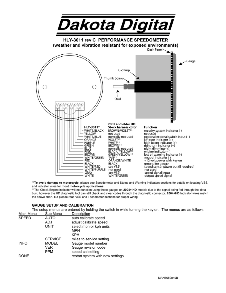
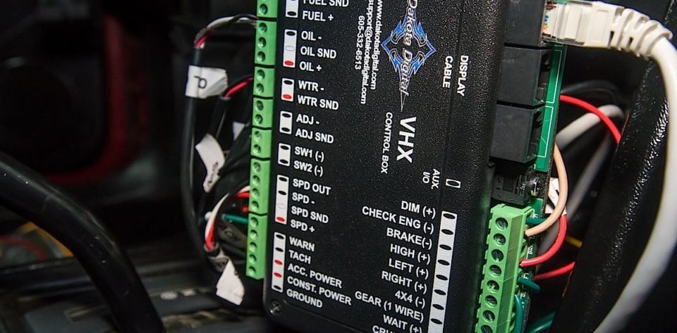
Black black twisted pair ground to the gauge white gray twisted pair speed signal to the speed input. Dakota digital manufactures digital instrumentation and accessories for the automotive motorcycle and car audio enthusiast. Furthermore dakota digital full instrument systems manufactured since 2011 provide even more functionality with the gps 50 2 displaying the compass heading. The red and black wires in the cable are power and ground 5v dc and their connection is discussed in spd and spd. The sensor has a 58 course thread fitting that accepts mid 80s and earlier cables directly. For newer cycles the speedometer cable will need to be replaced with one having the correct fitting.
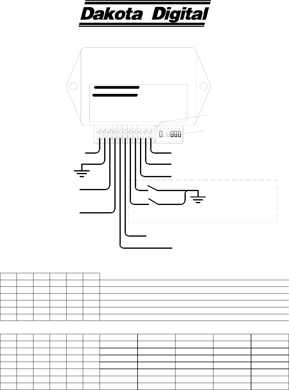
Speed tachometer fuel level voltmeter water temp and oil pressure. If you are using this sensor the white wire is the speed signal. Connect to spd snd. Speed t gps ready bt swright swleft display e buzzer quick start wiring diagram this drawing is a quick overview of the basic wiring for your new dakota digital hdx system. Your vehicle could start to act like it has a bad coil pack or throttle position sensor and after testing those you may still come up empty handed. Typical wiring for dakota digital products is.
For further wiring assistance please read the. Page 10 dakota digital supplies a 3 wire sensor for most of its kits. Pressure sensor sen 03 8 0 100 psi temp sensor sen 04 5 100 300 f r e ecuecm speed output red white black 12v key on power fused 5 20 amp max connect to main chassis ground ignition coil negative side ecuecm or ignition box tach output. Pressure sensor sen 03 8 0 100 psi temp sensor sen 04 5 100 300 f l e r o r ecuecm speed output white 12v key on power fused 5 20 amp max connect to main chassis ground ignition coil negative side ecuecm or ignition box tach output. Once completed all the basic functions should operate.
Gallery of Dakota Digital Speed Sensor Wiring Diagram