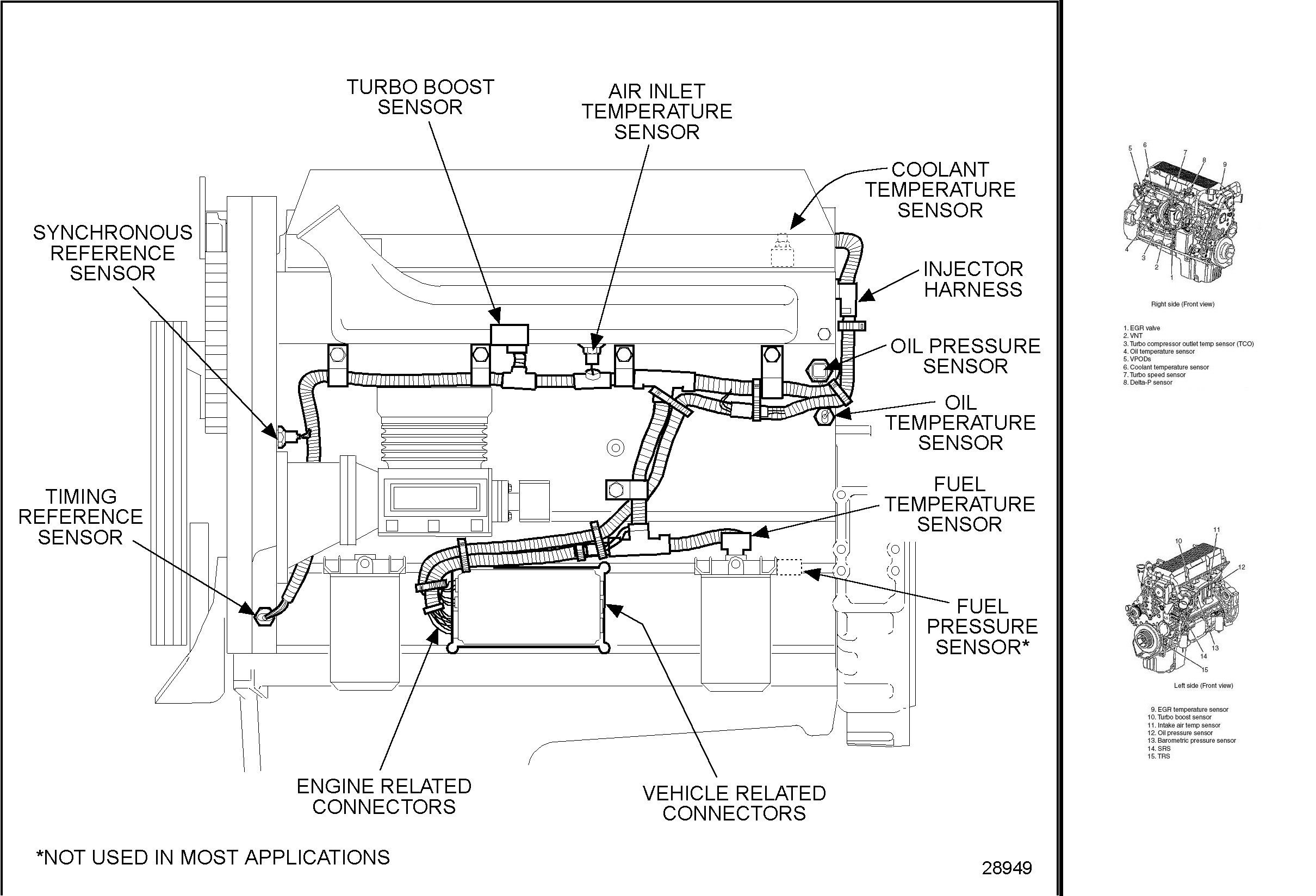
Depending upon application some units schematic diagram of ddec ii. Use live frog turnouts if possible.

Heatlink Ddc Actuator For Manifolds And Valves Heatlink
Ddc wiring diagram. Feed track power to all routes in and out of the turnout. Be very careful in wiring methods and workmanship. But i think its worth restating some of the basic concepts as part of this section as this is what i used as the basis of my own layout wiring described in the electrical systems subsection of my model railroad section. If we had a or or for every time weve been asked how to wire track and point work wed be writing this on a beach somewhere while sipping a cold beer. If atec is used connect this wire to atec ecm. Level the controller then insert screws into the two lower screws holes under the terminal block.
Leave no bare wire. Feed track power to all metal rails in the turnout. Feed track power to live frog using frog polarity switcher. Wiring a layout for dcc power layout wiring is fairly well documented and pretty simple when you come right down to it. For model ddec ii 2 mode use the wiring diagram for. A great layout needs good.
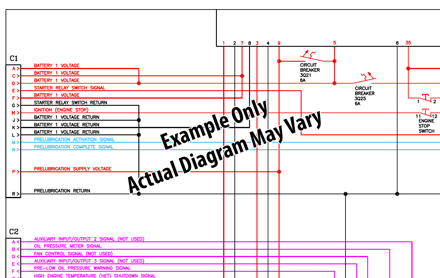
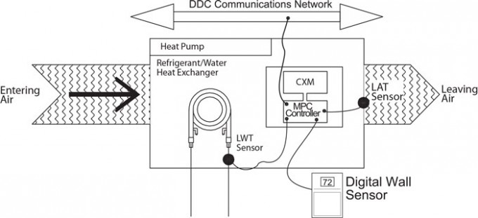
Simple multi meter is fine. Only lcd display and keypad allow for setpoint adjustment override and display of certain status and setpoints. Wiring point work special track conditions for dc or dcc wiring the track in plain english with diagrams. 3 for partial detailed views of the full view of the ddec ii wiring diagram. Page 21 oe217 02 g 0130l00118 e bus digital room sensor temp. Here are some recommendations for wiring turnouts on a dcc layout.
The ddec ii ecm is packaged in a. Connects to controller via fi eld wiring. Check for short circuits as you go before the booster is connected. The oe217 02 g is used with the ddc controller for room air temperature sensing applications. Remove the lower cover of the ddc controller. Connect the solenoid wires to the terminal block.
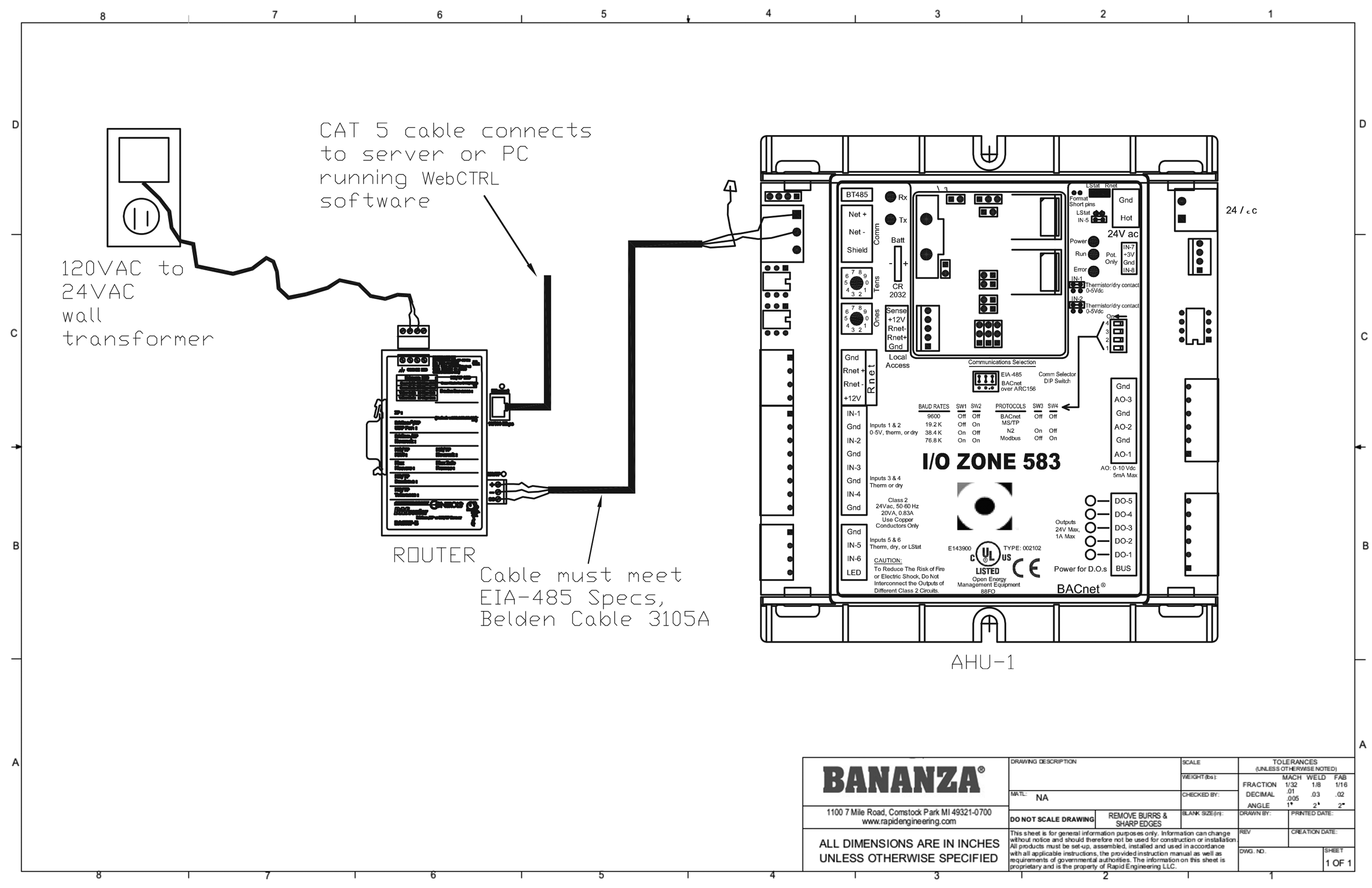
Direct digital control system index of drawings sheet description 1 title and cover page 2 supervisory controller 3 fcu wiring 5 ahu flow diagram 6 ahu 1 wiring diagram cover page pittsburgh air systems inc. Use with ddc controller only. Connect one wire from the solenoid to its respective station number on the. Please login to continue. Place the unit on the wall using the top screw slot. Wire cut off black wire and insulate end.
Dcc wiring clinic 9 dcc wiring basics ii with just one large block wiring mistakes and failures can be very hard to locate one defect anywhere and its no go everywhere. Please login to continue.
Gallery of Ddc Wiring Diagram