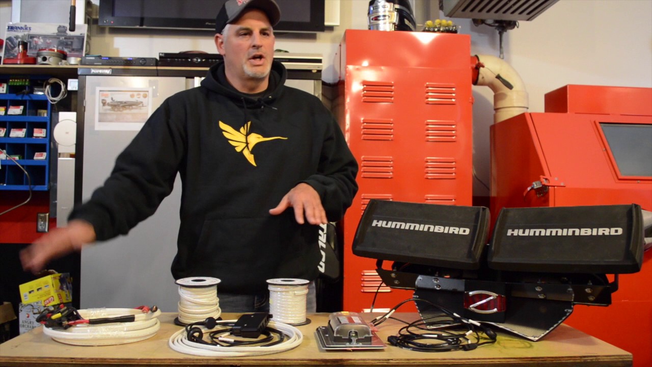
Last updated on october 3 2017there are a couple of things that may be unclear when looking to buy a fishfinder. Once youve chosen the most efficient one that provides precise data youll need to install it.
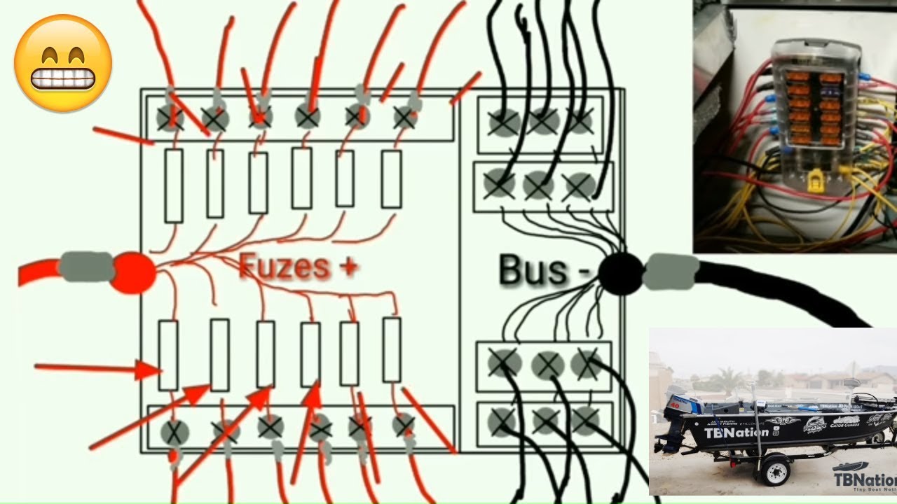
Boat Building Standards Basic Electricity Wiring Your Boat
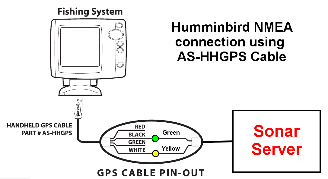
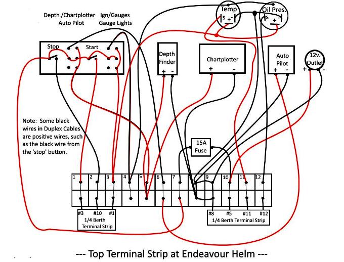
Depth finder wiring diagram. These diagrams are for the use of professional installers. 8608489271 toll free technical support. The depth finder wiring isnt shielded cable. Being that there are many different brands youll want to get the right one. This means that if you run it alongside or near any of your boats native wiring such as the wires for your power trim system youre likely to experience electrical interference that might interfere with the depth finders operation. Download diagram 11 for.
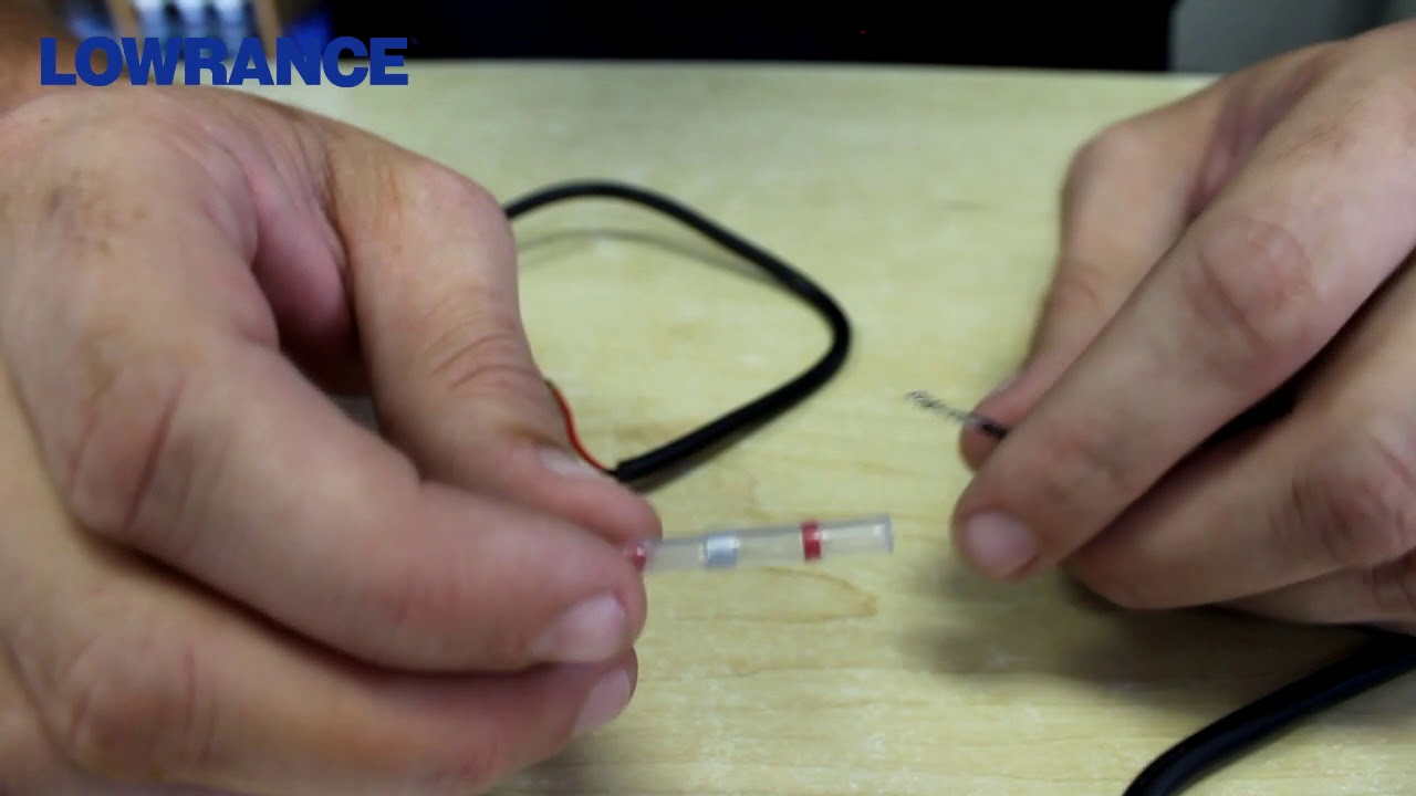
Smartcraft depth transducer wiring connections page 2 5 90 8m0063595 december 2011 2. Wiring diagrams for conventional non chirp transducers. If you run the depth finders wiring near your vhf radios. And this is where. Before attempting to rewire a transducer connector you should. Assemble the wire retainer securely into the connector.
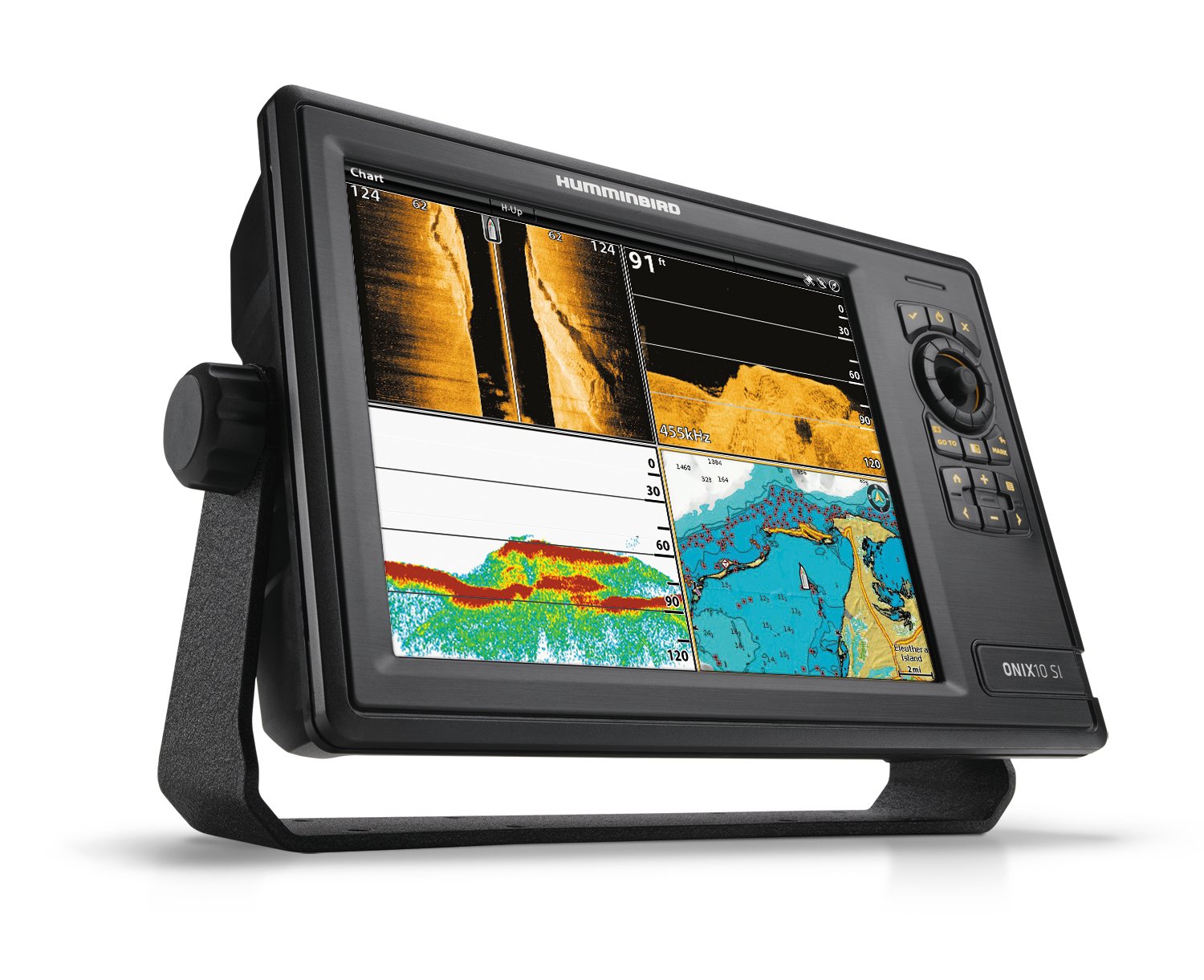
75 frontage road suite 106. A wire retainer b wire terminal c connector d assembled components e transducer connector. 1 humminbird console unit with side imaging and 2d sonar transducers with y cable for high space depth performance shop the setup. North stonington ct 06359 usa. Push each wire terminal into its respective position in the wire retainer until they snap in place. Check to see if an adapter cable exists see the adapters page.
Faria beede instruments inc.
Gallery of Depth Finder Wiring Diagram