Closed and will open during a defrost. When mode b is selected the.

Intermatic Defrost Timers And Manuals
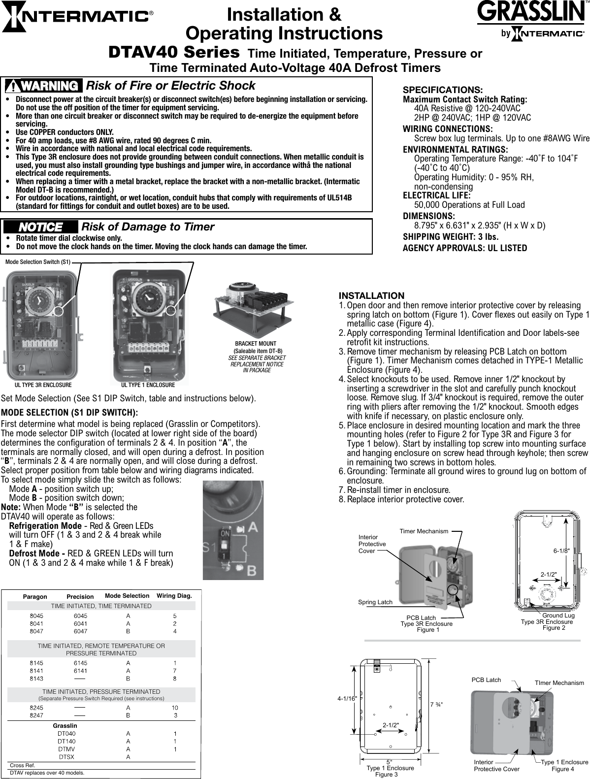
Dtsx b 240 wiring diagram. First determine what model is being replaced grasslin or competitors. Bracket mount 120 vac 240 vac 2 4 contacts 30a resistive at 120240vac 1hp at 120vac. In position b terminals 2 4 are normally open and will close during a defrost. Subscribe to our newsletter sign up for email alerts for products and software updates new product releases and information about upcoming events. Select proper position from table below and wiring diagrams indicated. When mode b is selected the dtav40 will operate as follows.
The dtsx contains a normally closed contact. Heatcraft defrost timer 40 amp 230v 60hz dtsx240 21340101. Mode b position switch down. To select mode simply slide the switch as follows. 1 wiring diagram model sizes 1 12 5 tons 208230 1. Refer to wiring diagrams 1 thru 12.
The wires on your new switch are intended for black power. The true 831994 defrost timer grasslin dtsx b 120 tm is the heart of the defrost system of a true refrigerator or freezer. 40a at 240 vac timing. Mode b position switch down. E lectric defrost wiring diagram 8047 r eplacement double pole s witching 4 s 1 position b with 8047 label applied. The dtav40 defrost control automatically selects the appropriate voltage between wiring diagrams.
2 rvs dts yel pnk speed up brnyel dft c y o w2 r e l g terminal block indoor unit red wht orn yel blk cb c y o w2 r e l w3 g blu pnk yelblu yelblu hps lps logic logic t2 cont c ctd t1 c y y dft dft rvs c r w2 o o schematic diagram ladder form. And red lights. Order from heritage parts the leading online provider of oem commercial kitchen replacement parts. The automatic defrost system prevents ice from building up on the evaporator coils by regularly suspending the refrigeration cycle and turning on heaters to melt any ice that may have accumulated. Dtsx a dtav40 ab per system time initiated time terminated paragon precisionsw1 8045 6045 a 8041 6041 a 8047 6047 b. Mode a position switch up.
To select mode simply slide the switch as follows. Check your wiring it sounds like its not right. Select proper position from table below and wiring diagrams indicated. Most parts ship same day. Mode a position switch up. Terminal block wiring diagram label sheet 8 x 12 sheet metal screws 3 6 x 12 hex head screws 4.
In position b terminals 2 4 are normally open and will close during a defrost.
Gallery of Dtsx B 240 Wiring Diagram