The neutral wire from the circuit is shared by both sets. In this gfci outlet wiring and installation diagram the combo switch outlet spst single way switch and ordinary outlet is connected to the load side of gfci.

How To Wire Switches
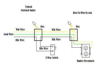
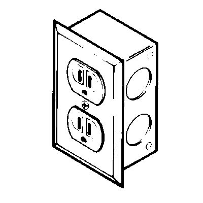
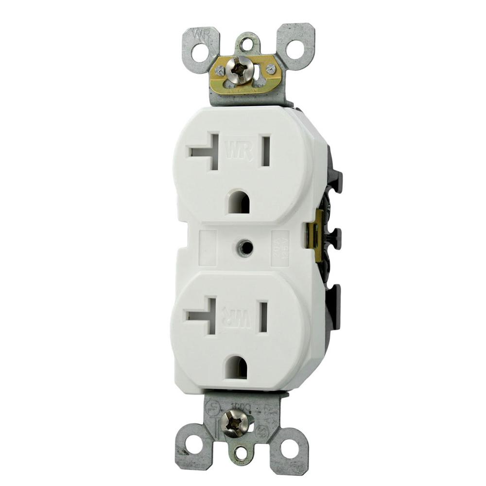
Duplex outlet wiring diagram. To wire multiple outlets follow the circuit diagrams posted in this article. Wiring a grounded duplex receptacle outlet this is a standard 15 amp 120 volt wall receptacle outlet wiring diagram. The long slot on the left is the neutral contact and the short slot is the hot contact. Here 3 wire cable is run from a double pole circuit breaker providing an independent 120 volts to two sets of multiple outlets. The bottom drawing shows how it is usually done. This is a polarized device.
The following two switched outlet wiring diagrams depict how split or half switched outlets can be wired. Wiring diagram for dual outlets. If you are going to install more than a single duplex receptacle in one location i prefer to use the dupelx receptacle wiring approach described in the article above. In this diagram both top and bottom receptacles are switched off on. The first one shows the method with the neutral conductor in the switch box. Wiring dual outlets in a series.
I have a problem with a duplex receptacle where the upper plug does not have power but the lower half does. With each outlet connected by its own pigtail wire if one fails because of physical damage the other wont be affected and should still work. The toggle switch in the combo switch outlet controls the first light bulb while the single way. Take notice that only a 3 wire cable is needed to perform this circuit. Split outlets are standard duplex outlets that have had their tabs cut to separate the top and bottom. Why is only half of the outlet working how to wire a half hot outlet and switched outlet.
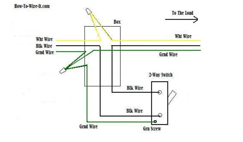
For wiring in series the terminal screws are the means for passing voltage from one receptacle to another. Two or more such receptacles can be ganged together in a box provided wiring circuit ampacity and connections are properly selected and installed. Wiring diagrams for half hot receptacles a full set of wiring diagrams about how to wire half hot and switched outlets. The diagram below will show how a standard switched duplex receptacle is wired. Multiple outlet in serie wiring diagram. Wiring for a switch and gfci receptacle in the same box is also shown.
In this diagram two duplex receptacle outlets are installed in the same box and wired separately to the source using pigtails spliced to connect the terminals of each one. This wiring is commonly used in a 20 amp kitchen circuit where two appliance feeds are needed such as for a refrigerator and a microwave in the same location. Included are diagrams for multiple gfcis a protected standard duplex receptacle and a protected light fixture. Any break or malfunction in one outlet will cause all the other outlets to fail. To wire a gfci circuit breaker see this link and wire a gfci switch combo at this link. Wiring a gfci outlet and a light switch.
It means all the connected loads to the load terminals of gfci are protected.
Gallery of Duplex Outlet Wiring Diagram