Wiring a gfci outlet with combo switch outlet receptacle light switch. This is a standard 15 amp 120 volt wall receptacle outlet wiring diagram.
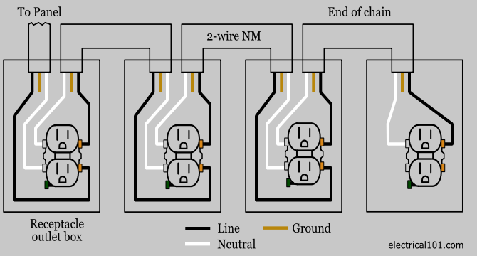
Split Receptacles Electrical 101
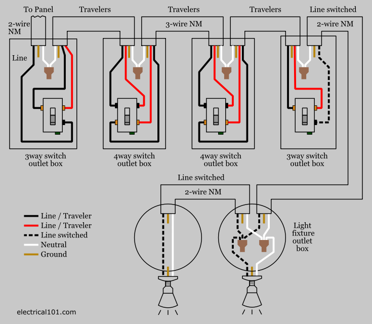
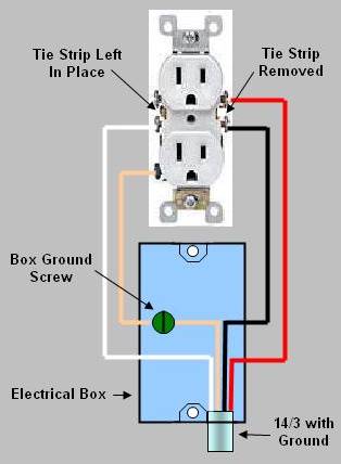
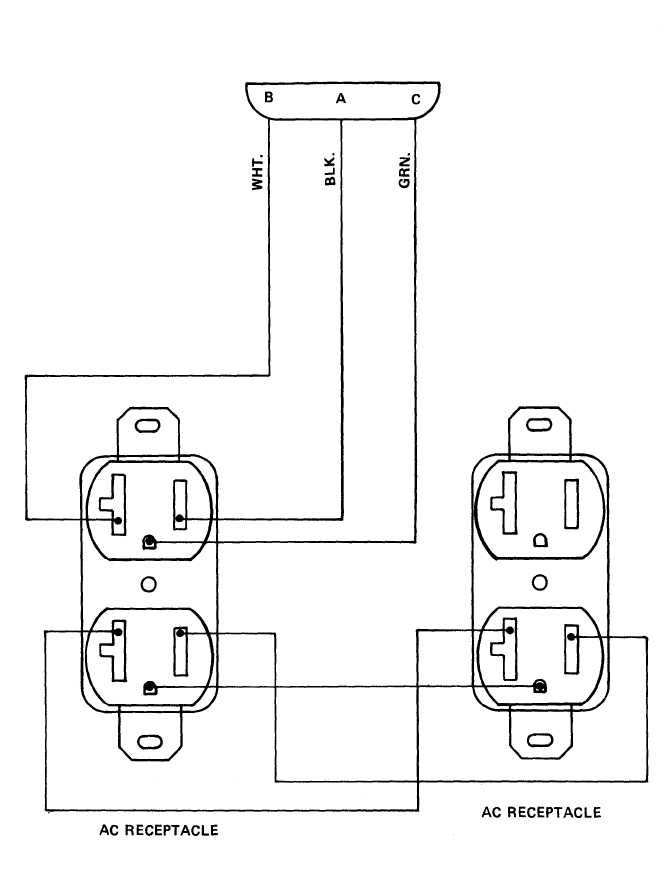
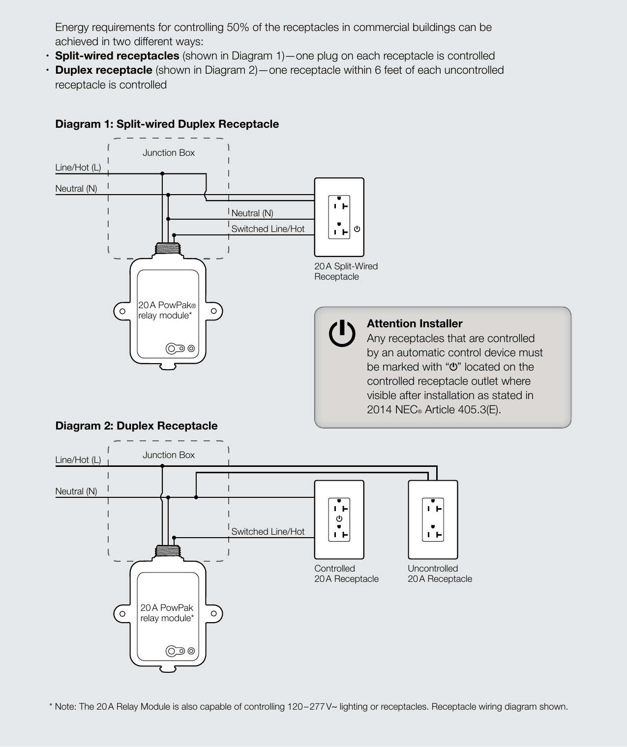
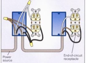
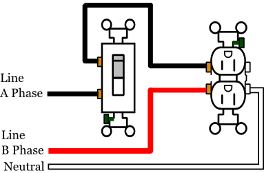
Duplex receptacle wiring diagram. In this gfci outlet wiring and installation diagram the combo switch outlet spst single way switch and ordinary outlet is connected to the load side of gfci. Depicted here is the wiring diagram for controlling the half of two duplex electrical receptacles by a wall switch without a neutral conductor. The long slot on the left is the neutral contact and the short slot is the hot contact. Wiring dual outlets in a series. In this diagram two duplex receptacle outlets are installed in the same box and wired separately to the source using pigtails spliced to connect the terminals of each one. Two or more such receptacles can be ganged together in a box provided wiring circuit ampacity and connections are properly selected and installed.
Dont use this receptacle when no ground wire is available. My light switch wiring diagrams may be helpful to you. This is a polarized device. A grounded contact at the bottom center is crescent shaped. Wiring a grounded duplex receptacle outlet. Wiring for multiple ground fault circuit interrupters gfci and standard duplex receptacles are included with protected and non protected arrangements.
If you are going to install more than a single duplex receptacle in one location i prefer to use the dupelx receptacle wiring approach described in the article above. Wiring multiple outlets in a series in this diagram wall outlets are wired in a row using the terminal screws to pass voltage from one receptacle to the next. With each outlet connected by its own pigtail wire if one fails because of physical damage the other wont be affected and should still work. Also shown is the half of the receptacle that is live at all times and the tab that must be cut in order to split the receptacles.
Gallery of Duplex Receptacle Wiring Diagram