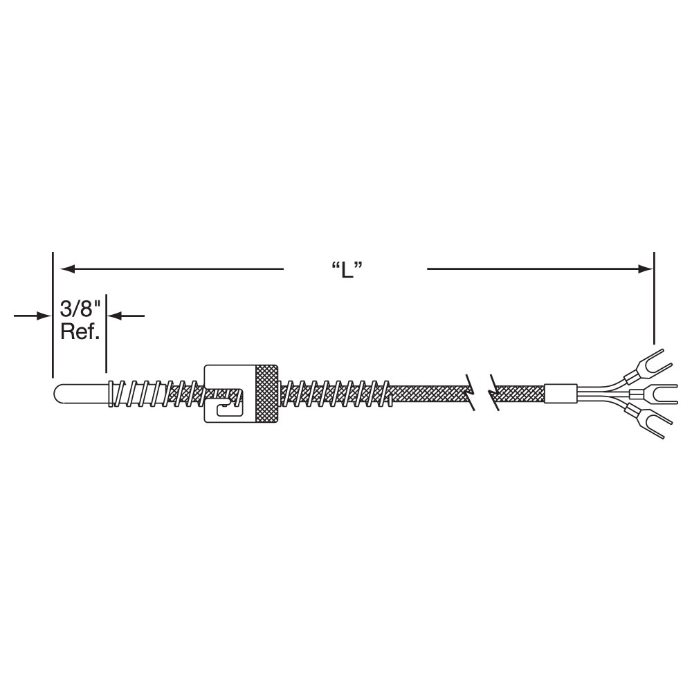
Because every pt100 element in the circuit containing the sensing elementincluding the lead wires connectors and the measuring instrument itselfwill introduce additional resistance into the circuit its important to be able to. There are 2 wiring methods for the rtd module and pt100 temperature sensors two wire and three wire connections.

Rx 4924 Thermocouple Wiring Schematic
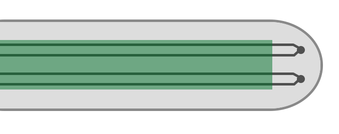
Duplex rtd pt100 wiring diagram. Duplex pt100 sensors use two junctions in one sensor. Mp82800r see page 70 for more info option c programmable rtd transmitter. Duplex 3 wire rtd connection as per single rtd but two individual element windings. For example heres the approximate resistances of a 4 wire pt100 rtd at 0 c for a pt1000 the middle resistance would be 1002 ω rather. Head mounted transmitter fully linearized pt100 input only. See page 70 for more info.
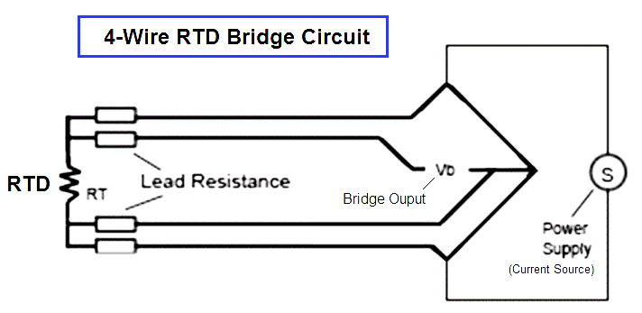
2 lead constructions result in leadwire resistance getting added to the element resistance. Each side of the rtd has two wires attached. When connected to the amplifier the smart amp will measure the voltage across the rtd and also across the wire pairs. 4 wire rtd signal connection connect each of the red leads on the positive side of the resistive element to the excitation positive and channel positive on the daq device. Cmc 141 multicon panel mount recorder controller 144x144mm. The graph below shows the temperature error from 2 leads of various sizes and lengths for a 100 ohm platinum rtd at 100c.
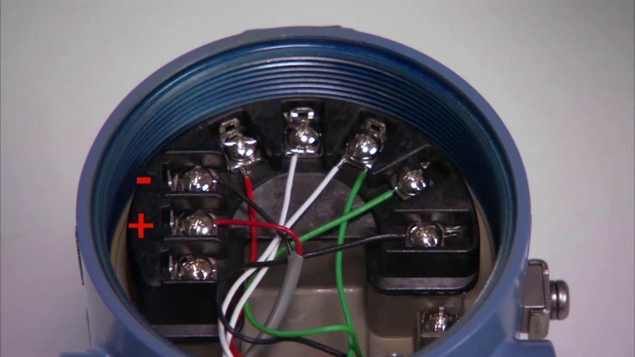
Option b rtd transmitter. Connect the black or white lead on the negative side for the resistive. 16 rtd ot 31 tc signals. Consequently the temperature reading is artificially high. 4 wire connection is the most accurate measurement. Rtd circuits work by sending a known amount of current through an rtd sensor and then measuring the voltage drop across that resistor at the given temperature.
Pt100 rtd 3 wire input only. Many instruments utilise this method of connection including temperature transmitters temperature controllers panel displays and data loggers and in many cases will not operate correctly if a 2 wire system is used. A1b1 a2b2 and c1c2. Three wire connection is by far the most common of all wiring types used in pt100 thermometry. Push button programmable can be programmed in the field. The following connection diagrams illustrate how to connect various rtd types to your daq device.
The instrument measures the lead resistance of all four lead wires removing these values for its reading. The multicon cmc are powerful and versatile compact multichannel controllers with a capability to record data if the recording function is requested and activated. Each wire is maybe 1 ω of resistance. Duplex pt100s are used in applications where downtime must be kept to a minimum one rtd element will be used until it reaches the end of its lifespan then the wire can be quickly swapped round to the other rtd element and a replacement sensor can be ordered. Head mount transmitter fully linearized. When wiring with two wires first jumper across a1 and b1and a2 and b2 respectively then connect pt100 sensors and to the rtd module according to the following diagram on the left.
Gallery of Duplex Rtd Pt100 Wiring Diagram