1 refer to the wiring diagrams provided with the control panel for proper panel connections and end of line resistor value. Catalog number 281b pl 282b pl 283b pl 284b pl ul temperature rating 135f 57c 194f 90c135f 57c.
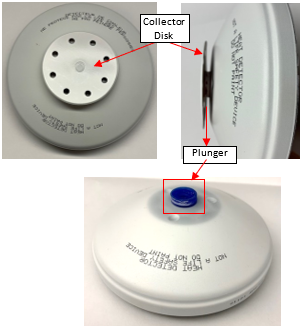
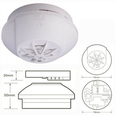
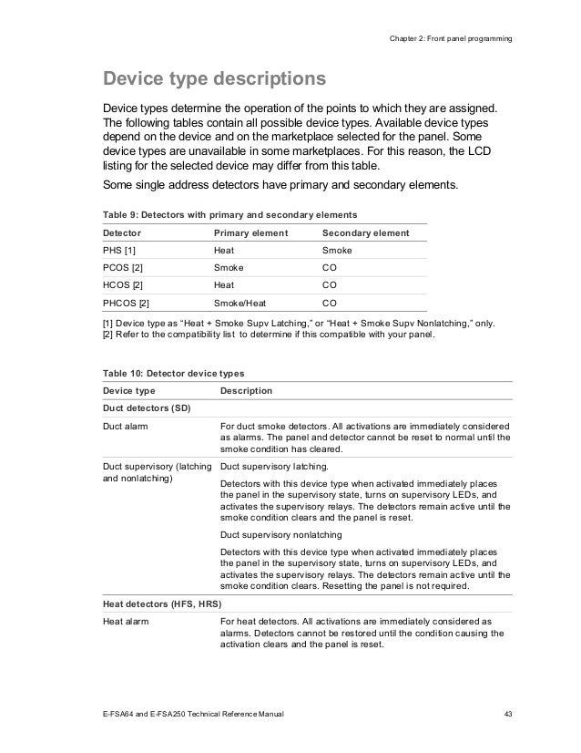
280 Series Mechanical Heat Detector
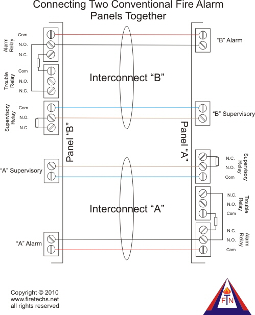
Edwards heat detector wiring diagram. When a smoke detector or pull station operates. This guidebook is for information only and is not intended as a substitute for verbatim legislated requirements. Note 1 this component is the fire resistor and its value is specified by the fire control. A smoke or heat detector can be installed to the existing or new home wiring. Dress the wiring neatly and then verify that the. Wiring practices manual edwards signaling products 90 fieldstone court cheshire ct 06410 1212.
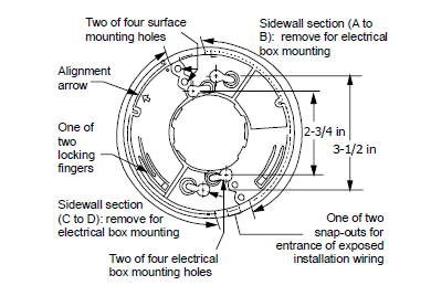
280b pl series heat detectors offer fixed temperature or combi nation rate of rise and fixed temperature detection. In our basic wiring diagram a single or multiple heat and smoke detectors are installed in the home by connecting the live line or hot neutral ground and an interconnected wire to the alarm. End of line resistor 1 heat detector listed fire alarm control panel 1 maintenance and testing the requirements for maintenance and testing of heat detectors are. To the appropriate terminals according to the wiring diagrams see figure 6 or figure 7. Esl 700 series conventional smoke and heat detector installation sheet description the esl 700 series smoke or smoke with rate of rise heat detectors have field replaceable optical chambers. Edwards 280b series heat sensors come standard with a white.
This is the basic fire alarm system used in household wiring. Consult the appropriate installation documents for wiring and configuration details. Wiring diagrams provided herein are for information and reference only and are not to be used for installation pur poses. Wiring diagram for connection of a single conventional detector to a zone. Wiring connections riser diagram and wire pull for some commonly used fire alarm circuits.
Gallery of Edwards Heat Detector Wiring Diagram