Connect the elcu to the emergency lighting for the area controlled. Haldex abs modal ecu wiring diagrams.

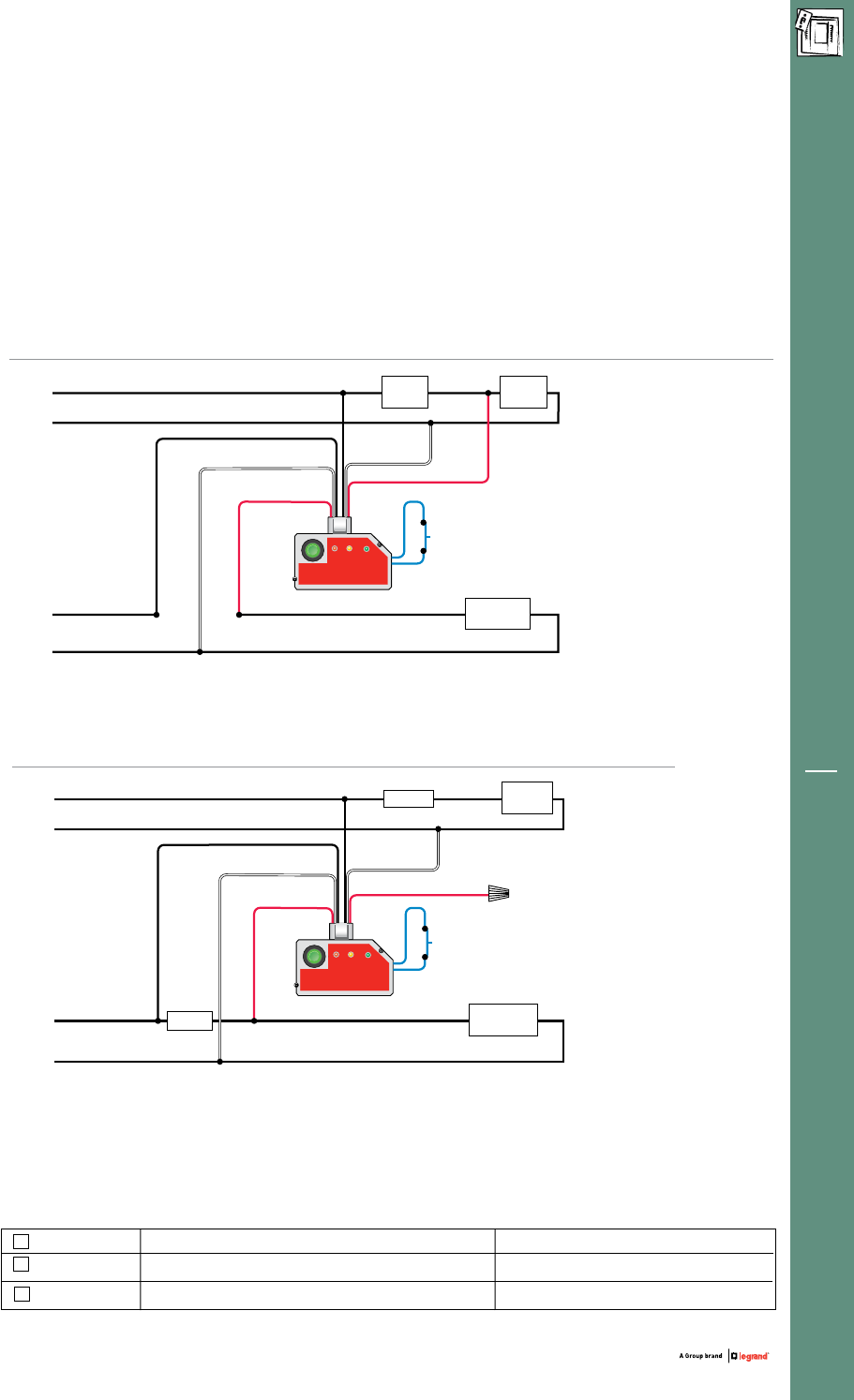
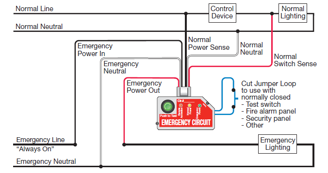
Legrand Emergency Lighting Test Switch Wiring Diagram 1
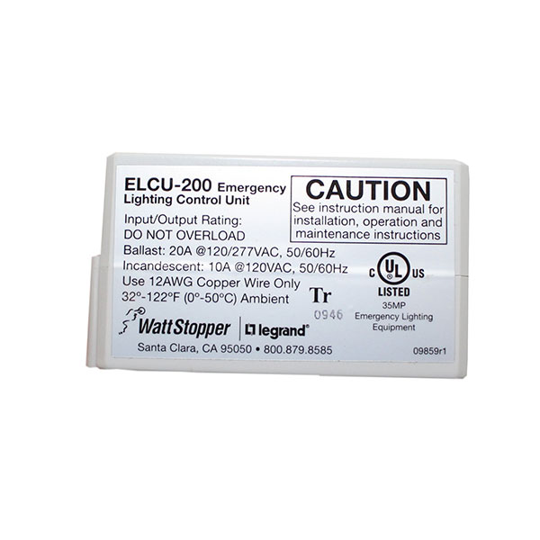
Elcu wiring diagram. The elcu is designed for lighting control in areas where emergency lighting fixtures are connected. Page 2 wiring reference table. Wattstoppers elcu emergency lighting control unit is a self contained device that allows any standard lighting control device to control emergency. Wattstoppers elcu 200 emergency lighting control unit is a self contained device that allows any standard lighting control device to control emergency lighting in conjunction with normal lighting in any area within a building. Mounting operation the elcu 200 monitors a single circuit that provides normal lighting to an area. Connect the emergency wiring leads on the elcu in series with the emergency lighting load as shown in the wiring diagram.
Jumper wire or that area. Connect the neutral for the emergency circuit to the emergency neutral lead as shown in the wiring diagram. Connect the elcu to the control device for the area controlled. The elcu 200 emergency lighting control unit allows lighting control devices for normal lighting and to also control emergency. Connect the neutral for the emergency circuit to the emergency neutral lead as shown in the wiring diagram. Modal ecu connector and power supply details.
Connect the elcu to the emergency lighting for the area controlled. Connect the emergency wiring leads on the elcu in series with the emergency lighting load as shown in the wiring diagram. Connect the elcus normal wiring leads to the normal lighting circuit as shown in the wiring diagram. Modal semi trailer wiring diagram for 2s1m 12v system 72kb. Wattstopper elcu emergency lighting control unit emergency lighting control unit v max load. Lighting installed within the area.
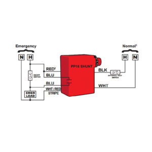
In normal power emergency power line out in neut emergency lighting emergency line emergency neutral sensing line switching line remote out 24vdc. The elcu can be wired either as a control device so. Modal semi trailer wiring diagram for 4s3m and 6s3m. Note that the normal power sense connection should be made to the line side of the control device that serves the same area as the emergency lighting. Modal full trailer wiring diagram for 4s3m and 6s3m. Elcu wiring diagrams jumper wire or normally closed input from test switch fire alarm input security input other remote in switch in line neut.
Gallery of Elcu Wiring Diagram