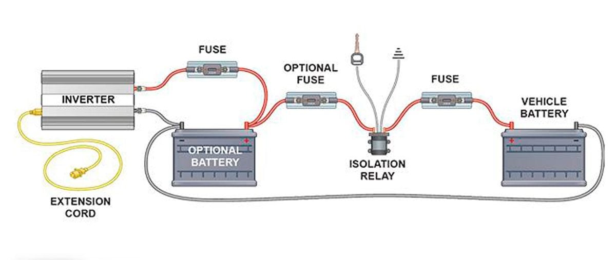
Emergency lighting equipment inverter sinusodial this product contains a rechargeable nickel cadmium battery. The purpose of emergency lighting is to ensure the lighting is provided promptly automatically and for a suitable time when the normal power supply to the lighting fails to ensure that people.
Synchron Dls Series Dual Lite
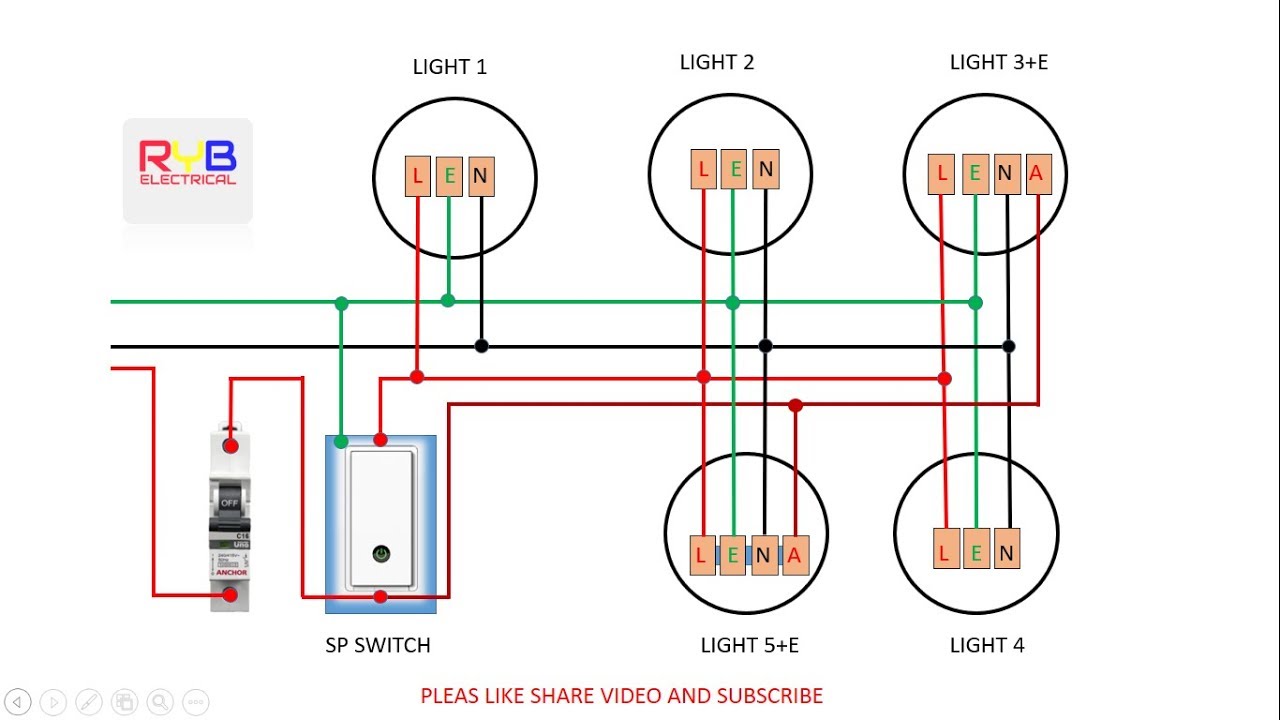
Emergency lighting inverter wiring diagram. Emergency lighting units em inverter type. Wiring diagram backup micro inverter and ac ballastdriver must be fed from the same branch circuit typical schematics only. The cli shall operate in conjunction with the existing. Typical wiring diagram emergency lighting mini central inverter system black white blue white brown black switched command signal violet earth ground green input wiring line switched output neutral normally on normally off output wiring neutral light fixtures led hid incandescent or fluorescent cap off unused wires diagram 1. Consult the factory for other wiring diagrams. 2 summary generalpresentation page12 singlephasecompactsystems page34 singlephaseinterruptiblesystems page56 singlephasefasttransfersystems page78.
If a diagram cannot be found within this selection consult customer service. Wiring your emergency lighting using a mini inverter in switched normally on lights multiple swi wiring diagram one 0 10v dimming control wiring your emergency lighting using a mini inverter in 0 10v lighting dimming control override. Ul924 ensures that the battery backup system has passed several critical discharge and recharge tests which are required for life safety. Online emergency central lighting inverter cli technical specifications part 1 general 11 summary a. Ul924 listed emergency lighting inverters. Subect to change without notice.
When selecting an emergency lighting inverter ups for emergency lighting it is mandatory that the system is ul924 listed. This specification describes a three phase on line double conversion solid state lighting inverter system utilizing patented ecm technology here after referred to as the cli. Wiring diagrams and installation examples page 14 em basic 230 240 v 5060 hz basic version tc del tc l tc dd tc sel tc tel t5 t8. The diagrams are categorized primarily according to the number of lamps in the. The emergency ballast wiring guide this document has been customized to contain a wide library of individual dia grams for various installation applications.
Gallery of Emergency Lighting Inverter Wiring Diagram