It is intended for trained installers who are familiar with all applicable codes and regulations. Chapter 7 front panel programming.
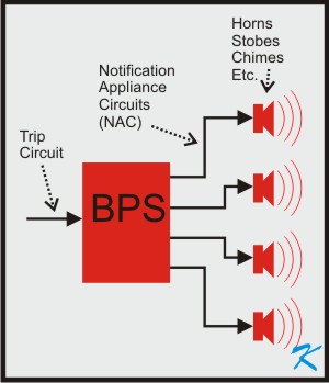
What Is A Booster Power Supply Or Signal Power Expander
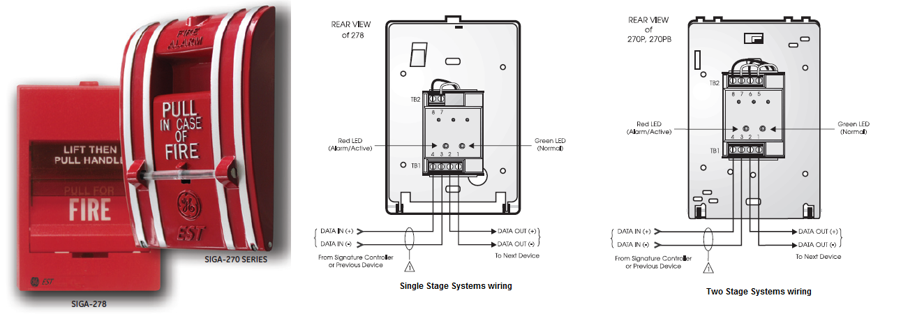
Est fire alarm panel wiring diagram. Provides instructions for programming the fire alarm system from the control panel cpudisplay unit. Ity code configures the module to provide synchronization of fire alarm signals across multiple zones. A wiring diagram is a simplified standard photographic depiction of an electric circuit. It reveals the elements of the circuit as simplified shapes as well as the power and signal connections between the gadgets. Alarm zone device type fire zone device type matrix group device type and group device activation count y 1 to 255 1 to 255 10. The following illustrations show schematics wiring connections riser diagram and wire pull for some commonly used fire alarm circuits.
Wire guide tm edwards systems technology installers. Requirements for est products and systems fire alarm security access control cctv. Branch speaker wiring 425 troubleshooting 427 chapter 5 installation 51. In the tables the letters are listed. It functions as a signal power 24 vdc riser selector. A short circuit will cause the fire alarm control panel to inhibit the activation of the audiblevisual signal.
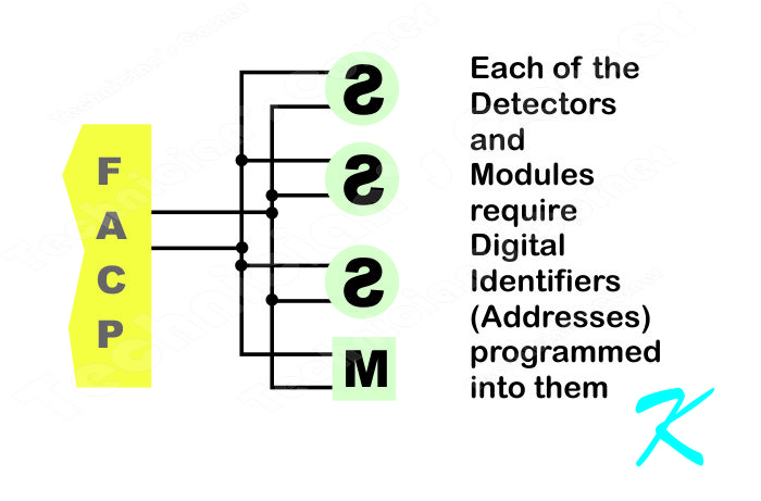
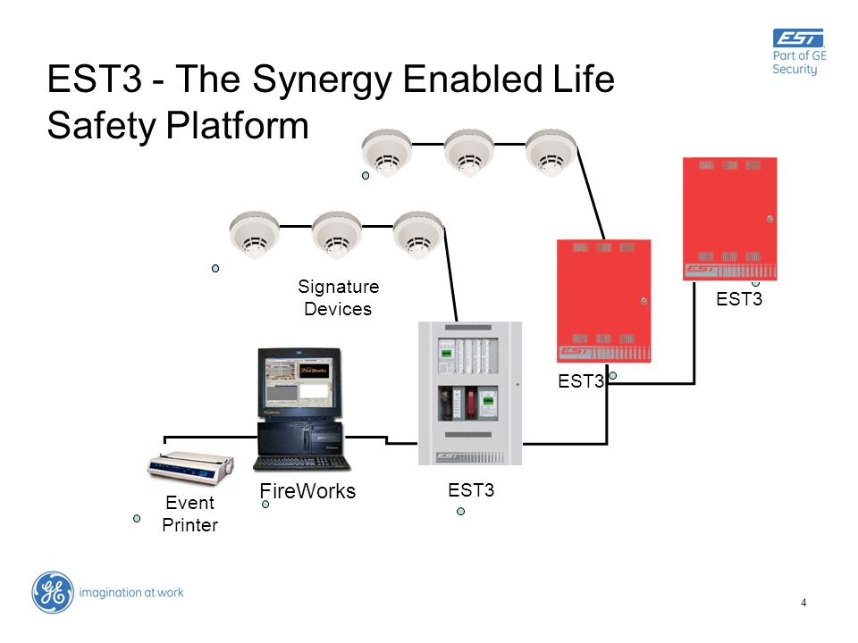
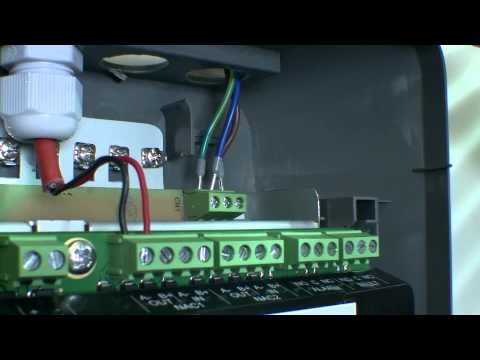
Variety of addressable fire alarm system wiring diagram. Indicating appliance circuits connect the fire alarm panel to the components which alert building occupants of the fire ie bells horns speakers strobe lights etc. The circuit type is designated with a letter a z. Est3 installation and service manual i content document history iv. The information shown for each control panel includes wiring diagrams and circuit tables. The output wiring is monitored for open circuits and short circuits.
It is intended for those trained and authorized to program the fire alarm system.
Gallery of Est Fire Alarm Panel Wiring Diagram