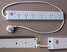
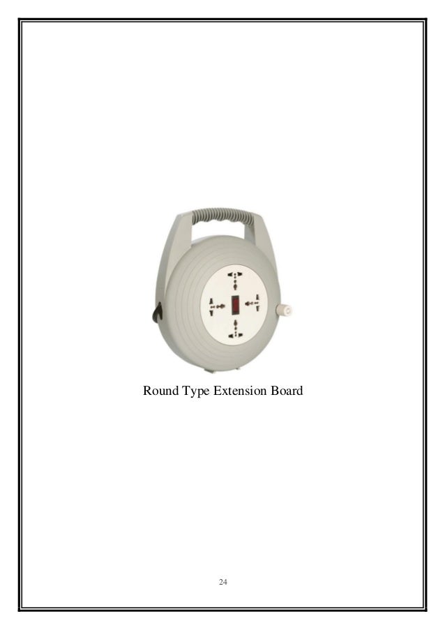
Wiring connection of electrical extension board how to make extension box get more great videos subscribe httpsgooglagwvy1 photos. An extension cord also called an extension lead or power extender is a power supply expanding the box.

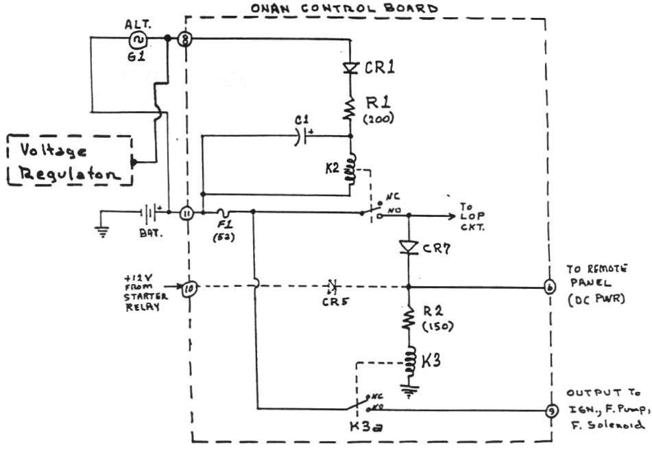
Designing Electrical Control Board General Technical
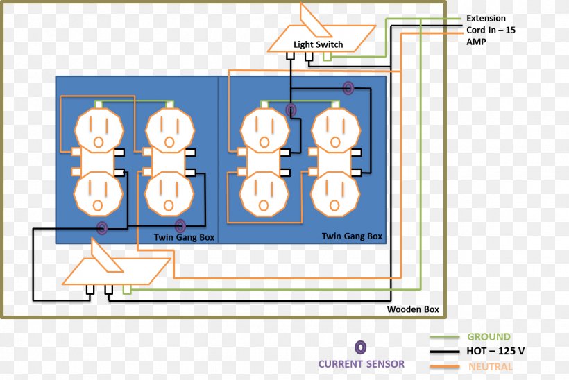
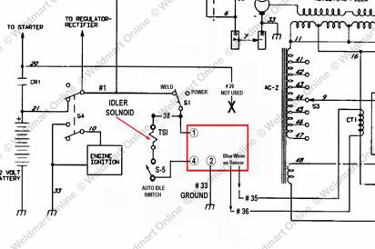
Extension board wiring diagram. The neutral wire is connected to the volt meter and each outlet. From the output side of overload protector the line wire goes to volt meter and all three outlets. In this step by step instructable i will show you wiring in the extension board. But it is necessary to have correct knowledge about wiring in the board. It is a lengthy flexible electrical cable with a plug at one end and multiple sockets on the other end. 1 pvc box for 7 point 2 switches 3pc 3 socket 3pc 4 fuse 1pc 5 wire please subscribe my.
The line wire is connected to the resettable thermal overload protector. Follow all instruction step by step and make your own extension board at home. It is a lengthy flexible electrical cable with a plug at one end and multiple sockets on the other end. Extension board is used for many purposes to extend the mains line. Presented here is an instructable to make your own extension board. Extension cord wiring diagram.
In the above extension board diagram the neutral and line wire supply comes to the board. By admin published april 16 2017 updated january 31 2019. Parts of this projects. Extension cord wiring diagram an extension cord also called an extension lead or power extender is a power supply expanding the box.
Gallery of Extension Board Wiring Diagram


/cdn.vox-cdn.com/uploads/chorus_asset/file/19585969/wiring_problems_xl_banner.jpg)