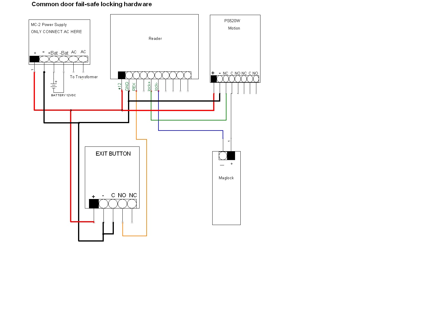
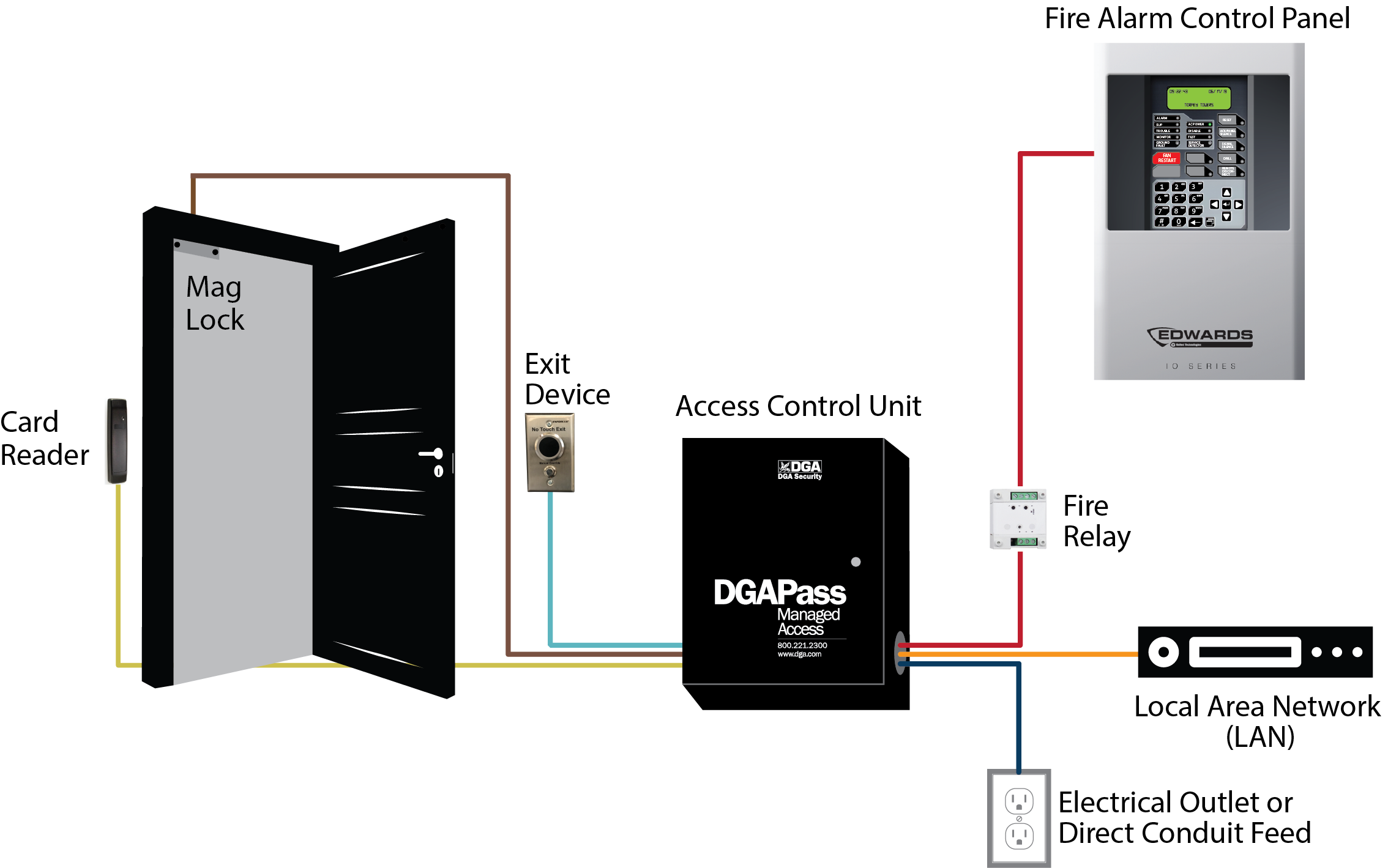
The door strike maglock must not share power with the actatek. Power supply may be ac or dc depending on the requirements of the strike.

Electric Strike Wiring Diagram Electric Strike Evolution 19
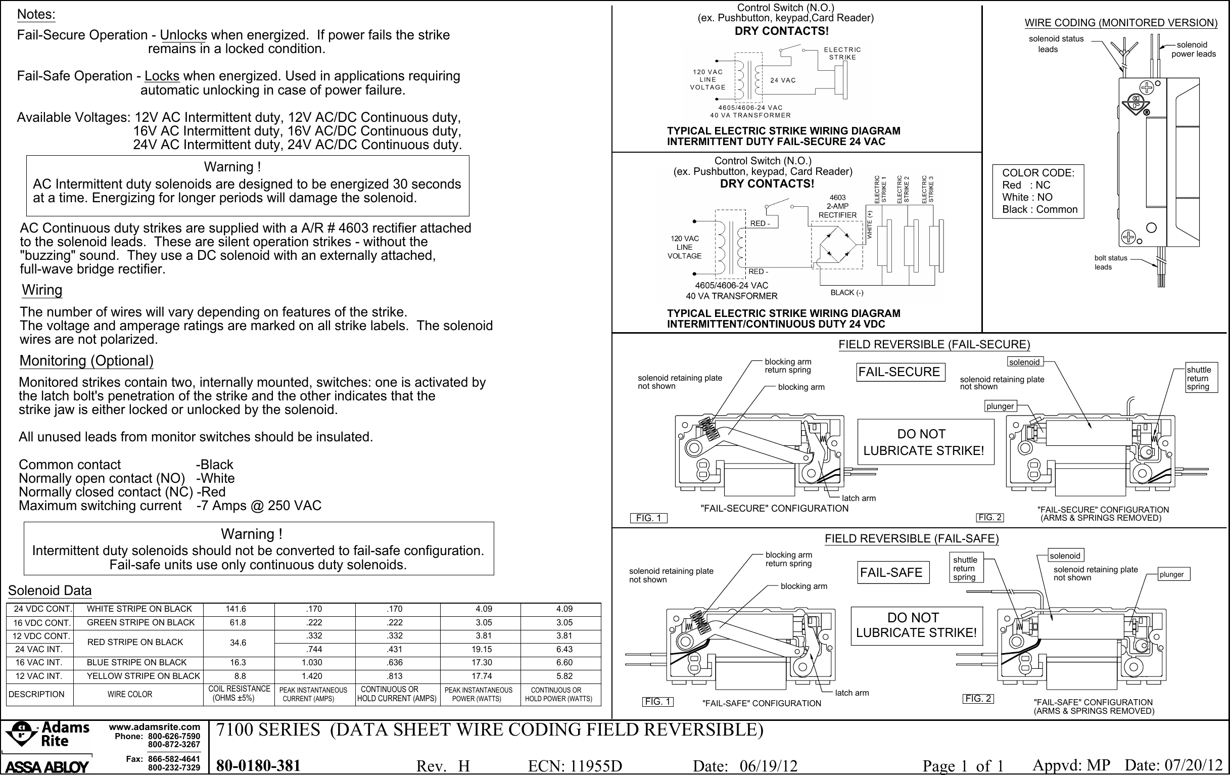
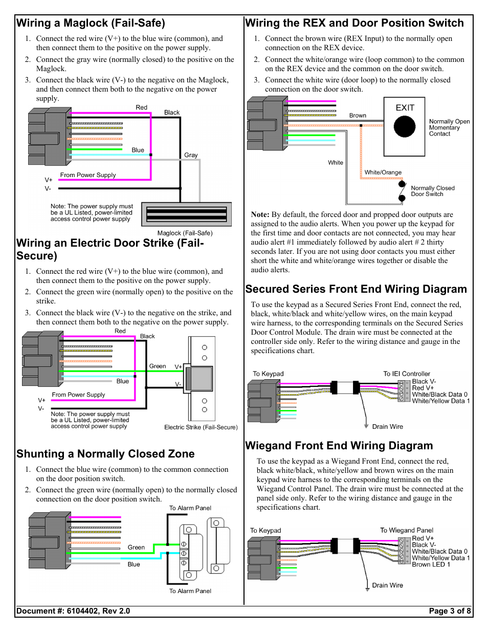
Fail secure wiring diagram. The following common wiring diagrams are available. For two door or tamdem applications. Fail safe versions allow exit in the event of power failure. Fail secure not working. When looking at fail safe locks this means that its default state is actually unlocked. To keep it locked during normal business operations power is applied.
Electric latch retraction with auto operator. One single door with panic bar. Proper operating voltage must be supplied to the strike if it is to function correctly. Figure 22 terminate lock wiring ca250b. Actatek supports 12vdc door strikes maglocks with a maximum current draw not exceeding 1amp. The lock unlocks when power is applied.
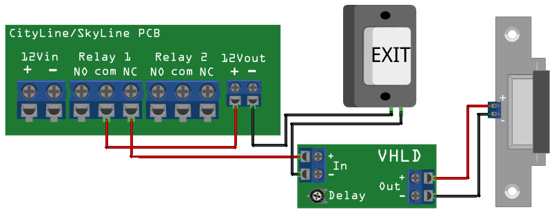
Fail secure lock wiring psp 24 fail secure lock black stripe black purple whtblue blue. 4td wiring example fail secure 4td wiring example fail safe gnd nc2 c2 no2 i2 nc1 c1 no1 i1 sc gnd nc4 c4 no4 i4 nc3 c3 no3 i3 sc 4rl 120240 vac 5060hz access control 2 ept 2 or 10 el device 2. This product may be provided fail safe or fail secure. Common wiring diagrams. 1 spdt voltage output. Fail secure versions do not.
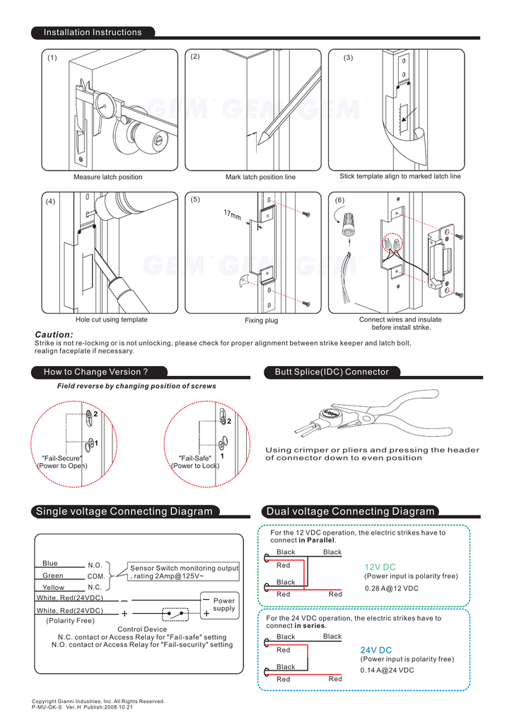
The next step is to have a fail safe method of cutting the power to the lock to ensure the where access control equipment is fitted to a fire escape door which includes an wiring break glass units and fire alarm interfaces the fib provides a switching. Fail safe door strike wiring diagram. An understanding of basic wiring diagrams fail safe and fail secure. An electric strike replaces the fixed strike faceplate often used with a latch bar. Wiring instructions fail secure strike with one button power supply push button no fail secure strike polarity insensitive depressing the push button would close the circui t allow power to flow and release the strike. The sdc acm 1 access control module is an magnetic lock or electric strike.
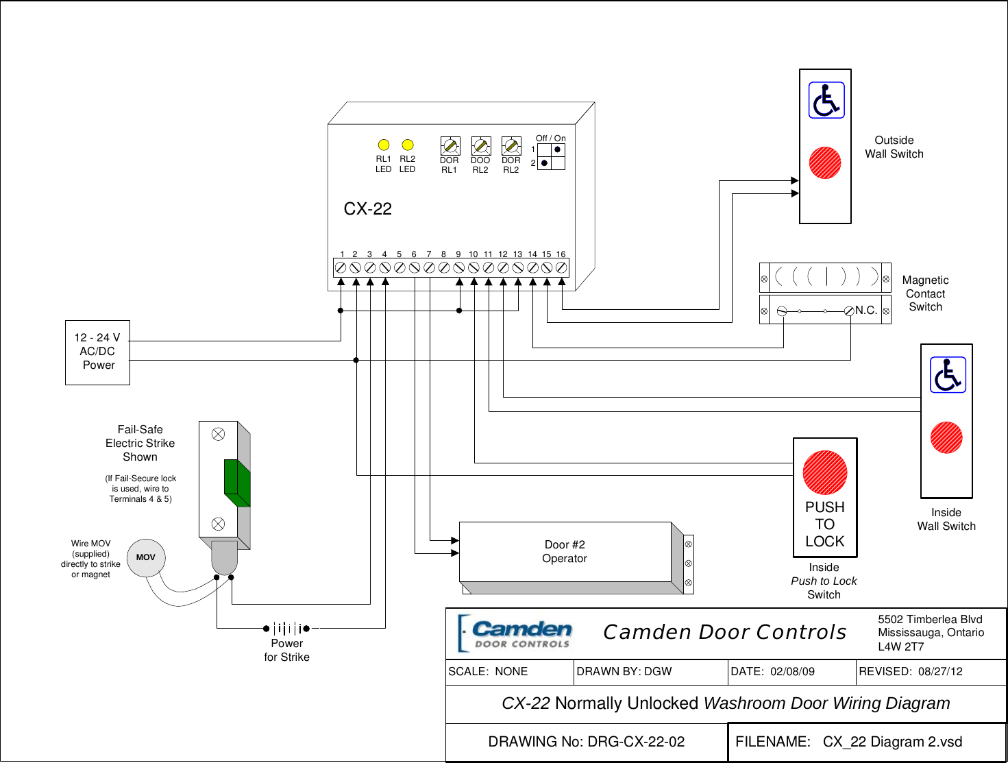
Latch function diagram. Fail secure not working. All switches shown in off position in wiring diagram enable time delay allows you to choose which outputs will have the below time delay. Figure 21 lock state fail secure device normally open relay board positon on relay door strike to common on dc power supply supply lock state lock supply fail secure device ki 00125e 07 11 keyscan inc. Electric latch retraction with auto operator. Diagram team system project open discussion and questions access control the basics exiting switches existing locksets.
It normally presents a ramped surface to the locking latch allowing the door to close and latch just like a fixed. Here is a great video about the door hardware fail secure vs fail safe. Connect all component negatives to the power supply negative. Technical guide pc109x 0415 page 34. Locking devices can be either fail safe or fail secure. Should the power be interrupted or fail the.
Do not attempt to use the power supply. Fail secure lock wiring step 1. A fail safe locking device unlocks when power is lost.
Gallery of Fail Secure Wiring Diagram