Ceiling fan motor circuit diagram. I connect the common wire connection with one connection connector and then i connect the run wire to the other wire connector as i shown in above diagram with blue color line.

Xa 3329 Exhaust Fan Capacitor Wiring Diagram Download Diagram
Fan wiring diagram with capacitor. So im thinking that the motor may have to start with the slower. Single phase motor wiring diagram with capacitor baldor single phase motor wiring diagram with capacitor single phase fan motor wiring diagram with capacitor single phase motor connection diagram with capacitor every electrical arrangement is made up of various unique pieces. Checking the motor and capacitor connections. However some people still struggle with the wiring part of the motor to the capacitor. How to wire a run capacitor to a motor blowers condensers sometimes when a blower or condenser fan motor goes bad a technician or even a diyer has issues wiring the new motor and capacitormost motors come with clear instructions or a wiring diagram on the side. 3 way fan switch wiring diagram.
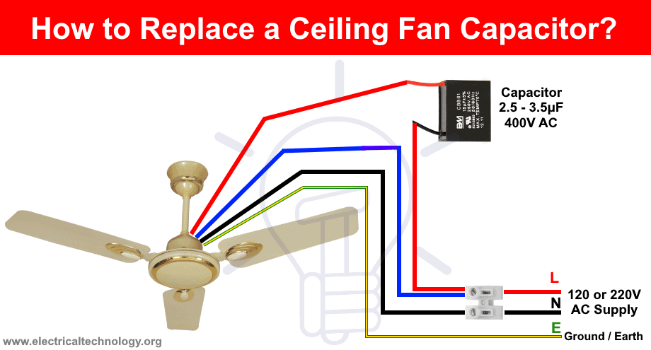
Generally the ceiling fan motors are split phase single phase ac motors. Ill provide a diagram and explain the wires below. Ac single phase capacitor start motor has two winding. In the above ceiling fan capacitor wiring diagram i shown a symbol diagram of fan motor winding in which i shown start run and common wires. Starting winding is also known as auxiliary winding while running windings is known as main winding. Black speed switch three wire capacitor.
How to verify fan motor wiring connections. One is starting winding and another is running winding. Each component ought to be placed and linked to different parts in particular manner. The concern is that there is a capacitor for the motor. Below is the circuit diagram of split phase induction motor in a ceiling fan clearly showing a capacitor connected in series with the starting winding auxiliary winding. I need a wire diagram for a 3 speed 3 wire switch and diagram of capacitor for a model tfp ceiling fan my guess is the capacitor is connected wrong and that is why i am only getting 2 speeds submitted.
5 years agoceiling fan speed switch repairhunter fan speed control. Double check your connections using the fan wiring diagrams. As always refer to the wiring diagram on the particular motor you are using. You should see that there is a separate motor winding for high speed. The common on the second 3 way switch is connected to the hot wires on the fanlight. Capacitor connection diagram of ceiling fan ceiling fan has a capacitor start motor in its inside.
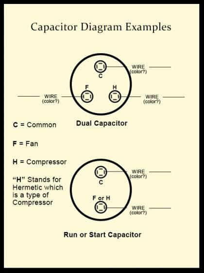
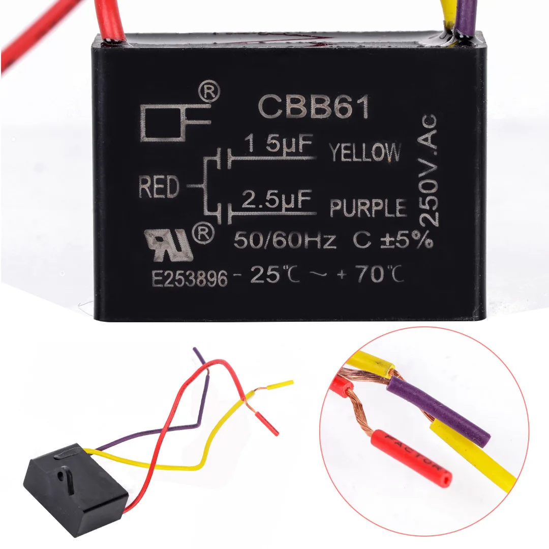
This is ac power and not a dual capacitor so the terminal side does not matter. Ceiling fan capacitor connection diagram. Cbb61 fan capacitor wiring diagram wiring diagram is a simplified conventional pictorial representation of an electrical circuit. To wire a 3 way switch circuit that controls both the fan and the light use this diagram. As with all 3 way circuits the common on one switch is connected to the hot source wire from the circuit. There are two windings inside the ceiling fan known as starting winding and running winding.
White wire from the condenser fan motor to one side of power on the contactor t1 and jumped to one side of the fan capacitor. Ceiling fan wiring diagram 1. Heres the 3 wire method. It shows the components of the circuit as simplified shapes and the capacity and signal connections in the company of the devices.
Gallery of Fan Wiring Diagram With Capacitor