Wiring diagrams index unit 50byn v ph hz label diagram fig. Uncontrolled when printed.

Electrical Engineering Fcu Fan Coil Unit Electrical Connection Details In English Hindi
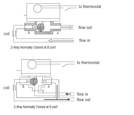
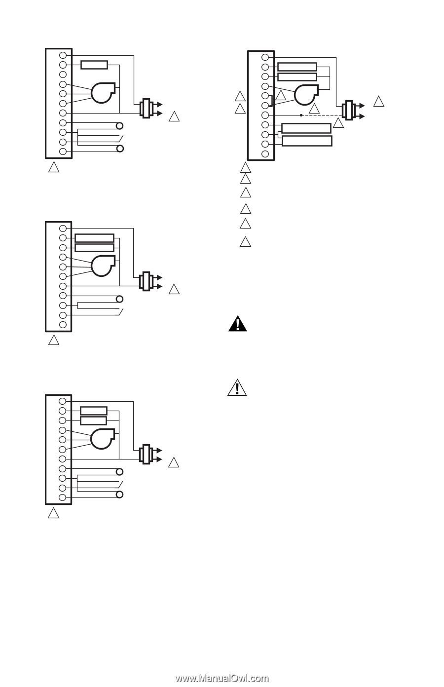
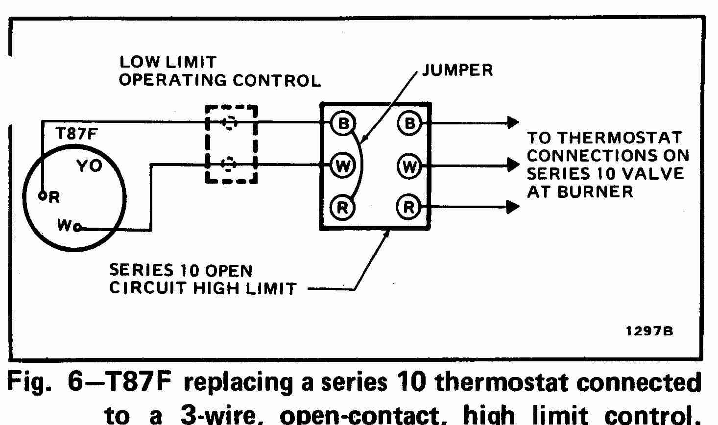
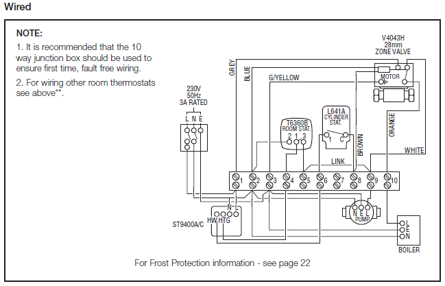
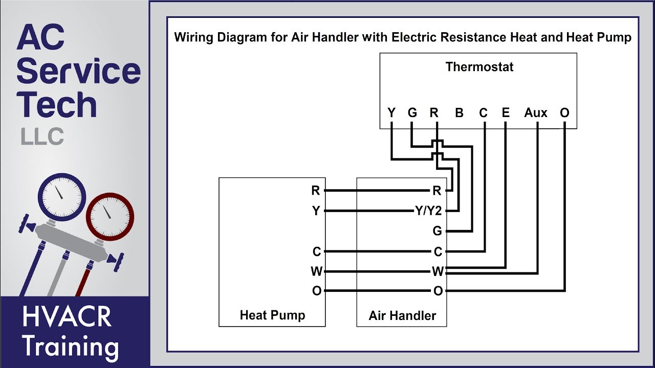
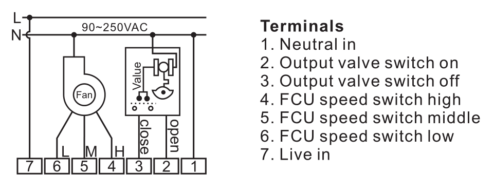
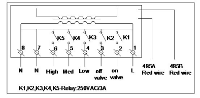
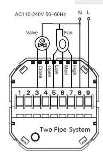
Fcu thermostat wiring diagram. Eti fcu fcrb installation operation and maintenance. Fcu digital controller provided by mscc. Thermostat provided by mscc. Thermostat wiring diagrams for heat pumps heat pump thermostat wire diagrams. No rl2 rl3 rl4 rlcom switch ac in gnd vs d d gnd d d vs gnd d d vs thermister low medium high 2 way 3 way valve 1030v 100240v rs 485 thermister ac dc. Provide with temperature readout set point adjust and unoccupied override button.
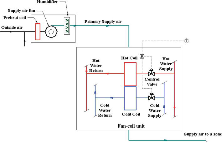
If fan speeds are adjustable the relay. Wiring diagram fcu tpd series thermostat sc series 4 ch relay board rl1com rl1nc rl1. Number 006 008 208230 3 60 460 3 60 11720011 c 1 575 3 60 012 208230 3 60 014 460 3 60 11720960 b 2 016 575 3 60 024 208230 3 60 460 3 60 1172007 c 3 575 3 60 accessory wiring unit 50byn accessory description fig. Number 006 024 winter start 4 evaporator defrost thermostat 5 temp. 1the mechanical systems control contractor mscc shall be. Primary drain pan high level sensor hhws 0 fcu control diagram not to scale filter supply fan t occupancy sensor notes.
My paperback and e book. May 2011 page 2 of 6. Heat pumps are different than air conditioners because a heat pump uses the process of refrigeration to heat and coolwhile an air conditioner uses the process of refrigeration to only cool the central air conditioner will usually be paired with a gas furnace an electric furnace or some other method of heating. 4 icp das co ltd. Verify fan speed will change from high medium and low by utilizing remote 3 speed switch thermostat or connecting by p18 to p15 p18 to p16 or p18 to p17.
Gallery of Fcu Thermostat Wiring Diagram