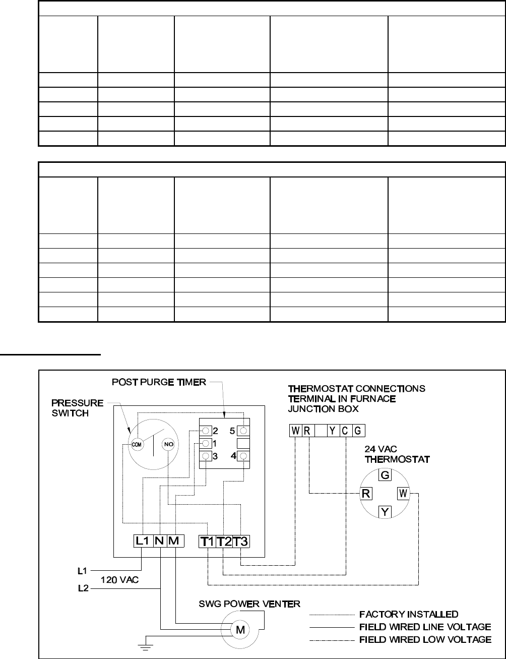
Diagrams a through e diagram a oil fired system. Wiring diagram for model cas 4mv power vent single 750mv gas appliance combustion air system.

Dometic Duo Therm 3312020 000 Oem Ccc2 Air Conditioner Control Box
Field controls power venter wiring diagram. Installation manual and wiring diagram for models pvg 100 pvg 300 and pvg 600 power venter systems. Cas 4mv ck 81 chimney vent single 750mv gas appliance wiring diagram. Simultaneous burner wiring. Voltage and safety control circuits between the venter and the appliance must be wired in accordance with the national electrical code for class i wiring or equivalent methods. It shows the components of the circuit as simplified shapes and the gift and signal associates along with the devices. Page 5 page 5.
2630 airport road kinston nc 28504 phone. Page 4 refer to the diagrams on the following page for guidance in wiring the power venter and control kit to the appliance. Power venting or sidewall vent is more economical and safer than a chimney vent. Fields power venter wiring diagram field controls 46457800 user manual fields power venter wiring diagram wiring diagram is a simplified welcome pictorial representation of an electrical circuit. Installation manual and wiring diagram for model pvo 300 and pvo 600 power venter systems. For complete installation information refer to the field controls swg 4at power venter installation manual for details pn 46306700 page 4.
Field controls direct vent systems fdvs field oil vent kits fovp and combovents cv. A power venter uses a motorized blower to vent the products of combustion. Wiring instructions wire the venter motor and controls in accordance with the national electrical code manufacturers recommendations andor applicable local codes. The wiring should be protected by an over current circuit device rated at 15 amperes. Route the venter motor and control wiring with an appropriate wiring method. Check ground circuit to make certain that the unit has been properly grounded.
For more information on field controls products wiring diagrams and installation manuals visit. The ck control has the ability to operate the oil burner motor up to 13 hp and diagram b oil fired system. Swg replacement motor kit instruction manual. A power venter is interlocked with the appliance to ensure that proper draft is achieved before the appliance burner is activated. Search the field controls wring diagram library for all wiring disgrams on field controls products. Controls kits for power venters for gas 750mv fired appliances.
Search by combustion air treatment or ventilation. Installation manual and wiring diagrams for models swg ii 5 swg ii 6 aga and swg 8 sidewall power venter kits.
Gallery of Field Controls Power Venter Wiring Diagram