An enphase team member may follow up with you about your feedback. Chat now with a gasboy sales representative to get your questions answered.

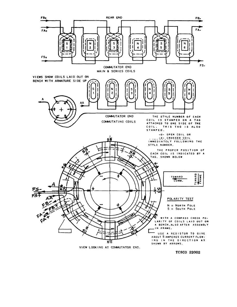
Image Of Field Test A Test Wiring Diagram B Field Test
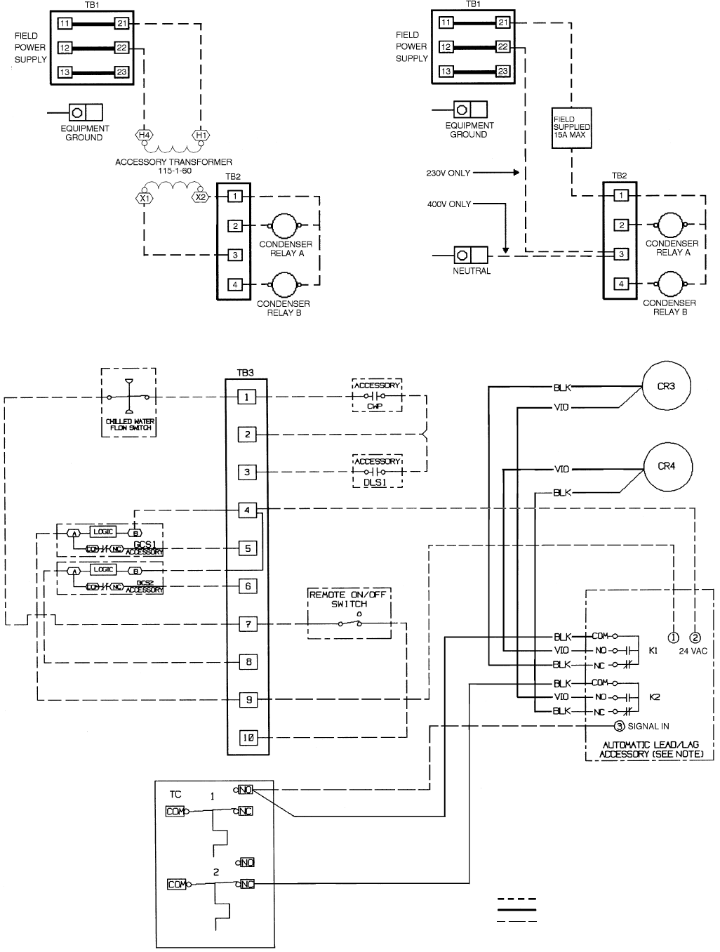
Field wiring diagram. Search the field controls wring diagram library for all wiring disgrams on field controls products. It shows how the electrical wires are interconnected and can also show where fixtures and components may be connected to the system. Search by combustion air treatment or ventilation. Topic see page introduction 1 1 product and part numbers 1 2 product description 1 2 product features 1 4 specifications 1 5 base panel modules 1 6 optional modules 1 9 location of tables and diagrams in this chapter. Dr power field and brush mowers parts diagrams. Fe 361 atlas master satellite field wiring diagram.
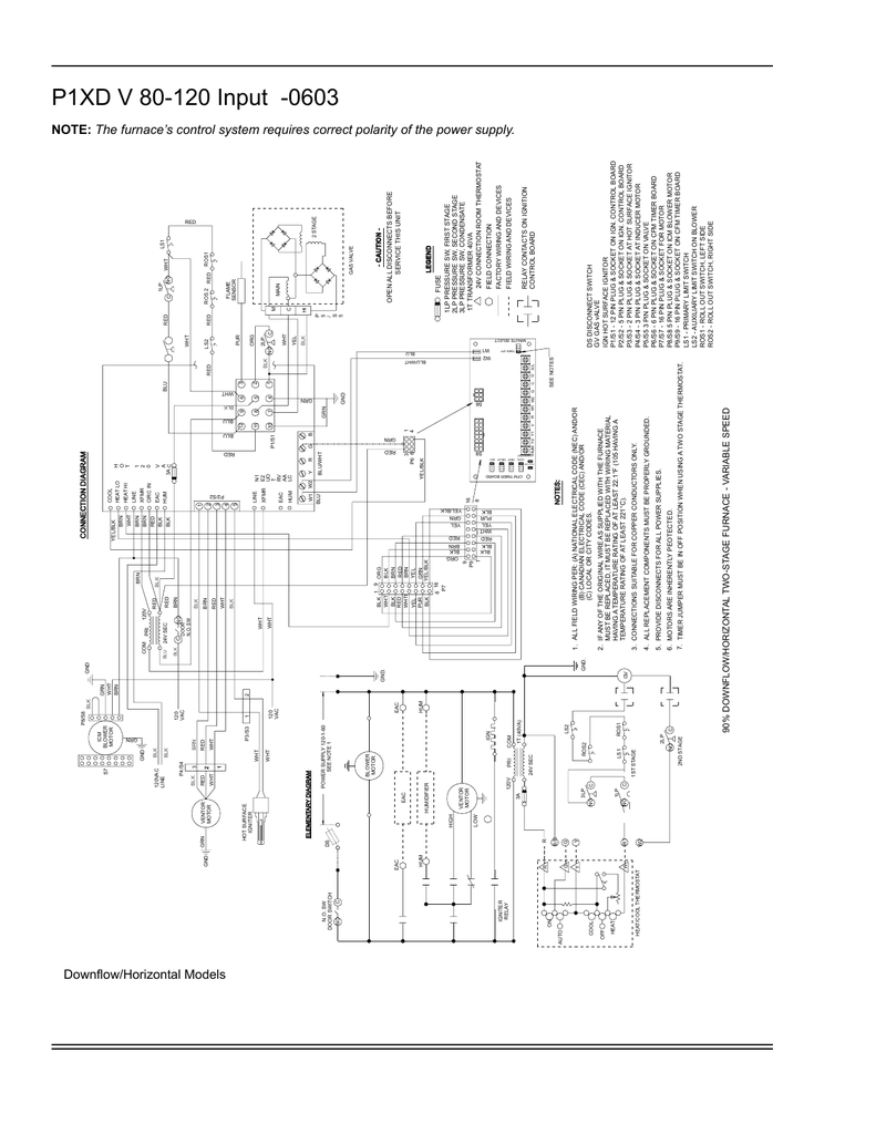
Model number coding system. When and how to use a wiring diagram. 4005 field wiring diagram 841 990 this chapter discusses the following topics. Tables and diagrams see page table 1 1. Shown in th e following table is a sample of typical unit model number and the coding system for each. Chat now with sales.
Knowledge of the nature of the signal source a suitable configuration of the data acquisition. The model numbers for the unit and the compressor are composed of numbers and lett ers that represent features of the equipment. Installation manual and wiring diagram for system control kit models ck 20f and ck 20fg for 30mv controlled natural or lp gas appliances with a pressure tap port in the gas valve. Fill out a form to request a quote from a gasboy sales specialist. Please help us improve. Updated feb 4 2020 overview.
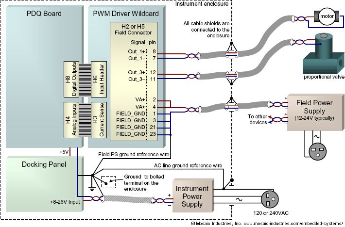
A wiring diagram is a simple visual representation of the physical connections and physical layout of an electrical system or circuit. Lists drawing numbers for unit wiring diagrams pueblo. Get a product quote. Cas 6 6sk 7 7sk installation manual wiring diagrams. Field wiring and noise considerations for analog signals. It shows the components of the circuit as simplified shapes and the power and signal connections between the devices.
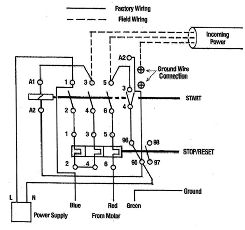
At1 walk behind mower ser atm to atm at2 walk behind mower ser atm to. A wiring diagram is a simplified conventional pictorial representation of an electrical circuit. Hi there save hours of searching online or wasting money on unnecessary repairs by talking to a 6ya expert who can help you resolve this. Unfortunately measuring analog signals with a data acquisition device is not always as simple as wiring the signal source leads to the data acquisition device. Attend a product demo. This is unlike a schematic diagram where the arrangement of the components interconnections on the diagram us.
A wiring diagram usually gives information about the relative position and arrangement of devices and terminals on the devices to help in building or servicing the device.
Gallery of Field Wiring Diagram