Version 105 revision a june 2011 part number 94100 00 eng 94100 00 eng cabling guide cfx 750 display. H 10 locknut clipper foot switch 522 b14 full guard with assembly.
I Can T Find A Wiring Diagram Orange Amps Forum
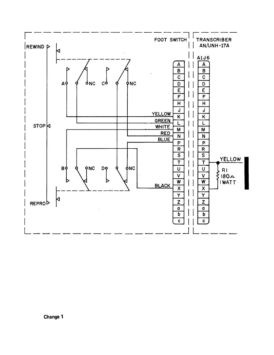
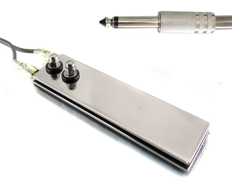
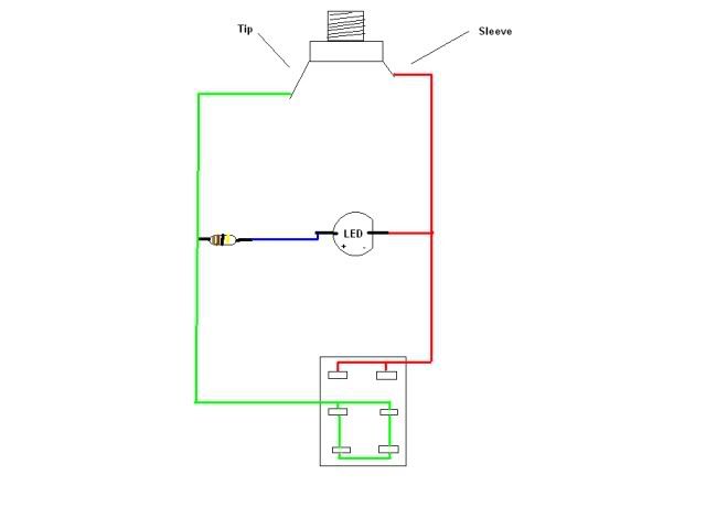
Foot switch wiring diagram. An initial look at a circuit representation might be complicated but if you. I used an old extension cord and cut a short piece for the socket side. Btw you can get lamp switches at ace hardware cheap. See diagram c form 522 f20 rev. Connection to relay terminal 4 nc relay terminal 14 t2 battery negative terminal connection to battery positive terminal battery negative terminal actuator terminal 2 black foot switch up wire battery positive terminal actuator terminal 1 red battery. Click on the image to enlarge and then save it to your computer by right.
Variety of foot switch wiring diagram. Clipper foot operated switches are furnished with two 732 in. To wire the actuator to the foot switch for double action extentionretraction make the connections between the foot switch power source battery relay and actuator wires as follows. Foot switch wiring diagram download. As the wiring shows we are really only wiring the black wires to the switch. 56 mmø diameter mounting holes on 2 78 in.
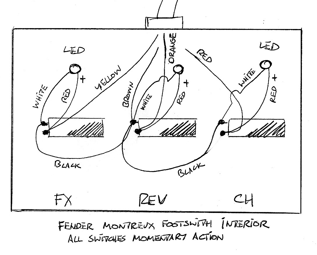
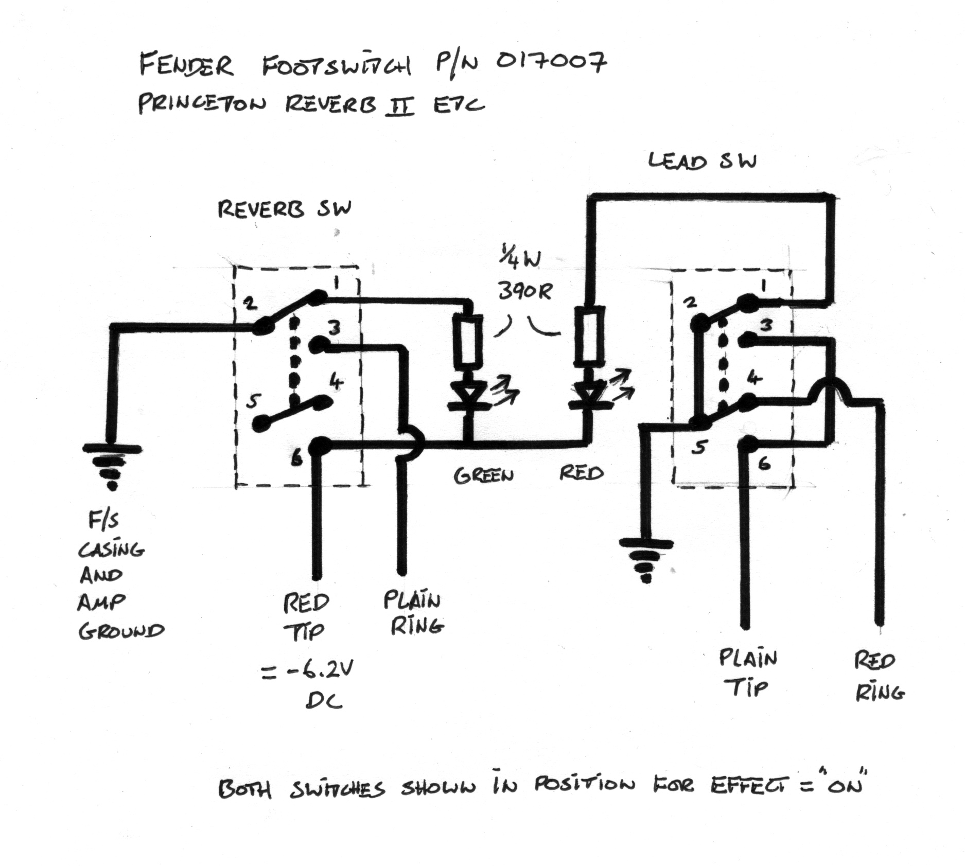
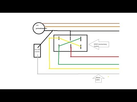
Building one without leds is seemple. Foot switch wiring diagram above is a simple diagram that shows how things get wired. Use two number 10 machine screws and two number 10 lock nuts when mounting foot switch to full guard. 2 wire plus shield cable 2 onoff switches a box and a trs plug. Foot switch wiring diagram. Shield is ground and goes to the sleeve of the trs plug and to one side of each switch one wire to each switch and the other end to the left over connectors on the plug.
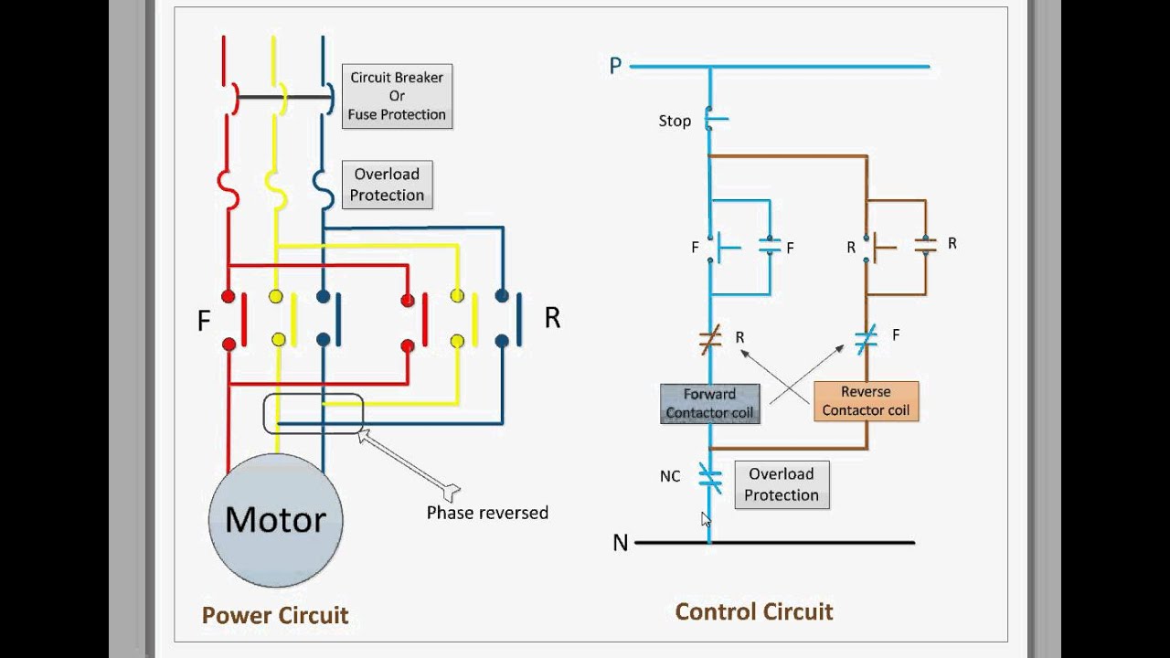
The wiring colors in the usa are black for hot white for neutral and green or greenyellow for ground. A newbie s overview to circuit diagrams.
Gallery of Foot Switch Wiring Diagram