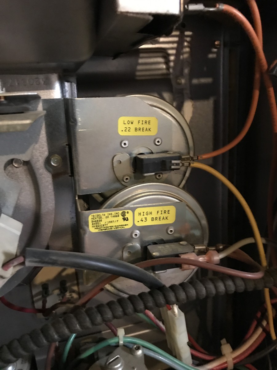
Pressure switches are used to stop the furnace from operating in an unsafe condition. Pressure switch location and connection if the pressure switch activates to shut the furnace down the vent and drain systems must be checked and cleared.

Pressure Sensor Amp Wiring Diagram
Furnace pressure switch wiring diagram. A furnace pressure switch is a safety device located near the draft inducer motor of a gas forced air furnace. The switch is there to prevent the furnace from running unless the correct venting air pressure is present. A simple pressure switch with a range of 50 to 350 bar can be made using a pressure sensor. Ensure the draft is above the required pressure. In this video we show you the best way to a pressure switch for 115v and 230v pumps. O flame sensor probe compressor contactor electronic air cleaner humidifier inducer circu lator blower 50a65 843 24 vac 120 vac 24 vac class ii transformer hot line neutral line th tr low voltage 24 vac line voltage 120 vac legend n.
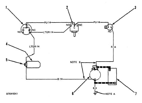
On newer furnaces on a call for heat the ifc checks the pressure switch. The plunger may not be pulling in completely and may only bob around when the pressure builds up inside the furnace. This method will work for any pump that runs directly off of a pressure switch including jet pumps well. If is in the closed position the furnace stops the sequence and goes into lockout mode until the switch is open. If you can accept somewhat reduced linearity the sensor can even be used up to 500 bar. Normally open switch typical system wiring diagram.
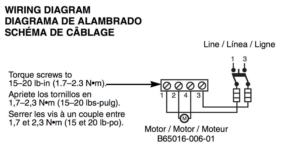
Ouvrez les disjoncteurs avant open all disconnects before 115vac line de proceder avec le service servicing this unit power factor not used on 12 hp motors choke valve 120vac. By this point on an 80 efficiency furnace if you havent found the culprit you will have to put on your best thinking cap because the issue could be any number of things including a bad board loose or bad. Wiring diagram wiring diagram 97 modulating condensing furnace with ecm motor caution precaution 115vac neut. Step 3 repair the pressure switch. As shown in the schematic diagram the circuit contains very few components other than the sensor. Hvac 30 delivers simulation based learning with over 25 interactive wiring diagrams and troubleshooting practice on 7 pieces of equipment with over 160 total faults.
Failure to do so may result in serious bodily harm or nuisance furnace shutdown andor a hazardous condition that may lead to property damage personal injury or death. The pressure switch has a pressure at which it closes which is typically negative. If your pressure switch is stuck it is most likely a problem in the running of the furnace. Using a cloth and a wire brush remove any blockages and dirt from the secondary exchanger and. Wiring diagram 1083292 uim a 0114 section xii. Normally closed switch n.
A pressure switch is designed to sense the negative pressure created by the draft inducer motor during the furnace startup and.
Gallery of Furnace Pressure Switch Wiring Diagram


:max_bytes(150000):strip_icc()/pressure-switches-56a4a21e3df78cf7728357f4.jpg)