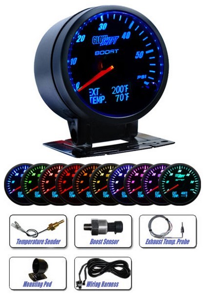
Wiring diagram for glowshift boost gauge thank you for visiting our site this is images about wiring diagram for glowshift boost gauge posted. Glowshifts tinted gauge series has been revamped from our previous gauge model in both performance and style.

Pyro Meter Vdo 12v Egt Gauge Kit 4wd Truck
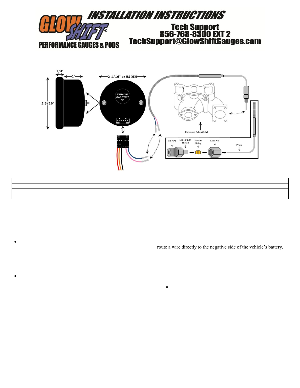
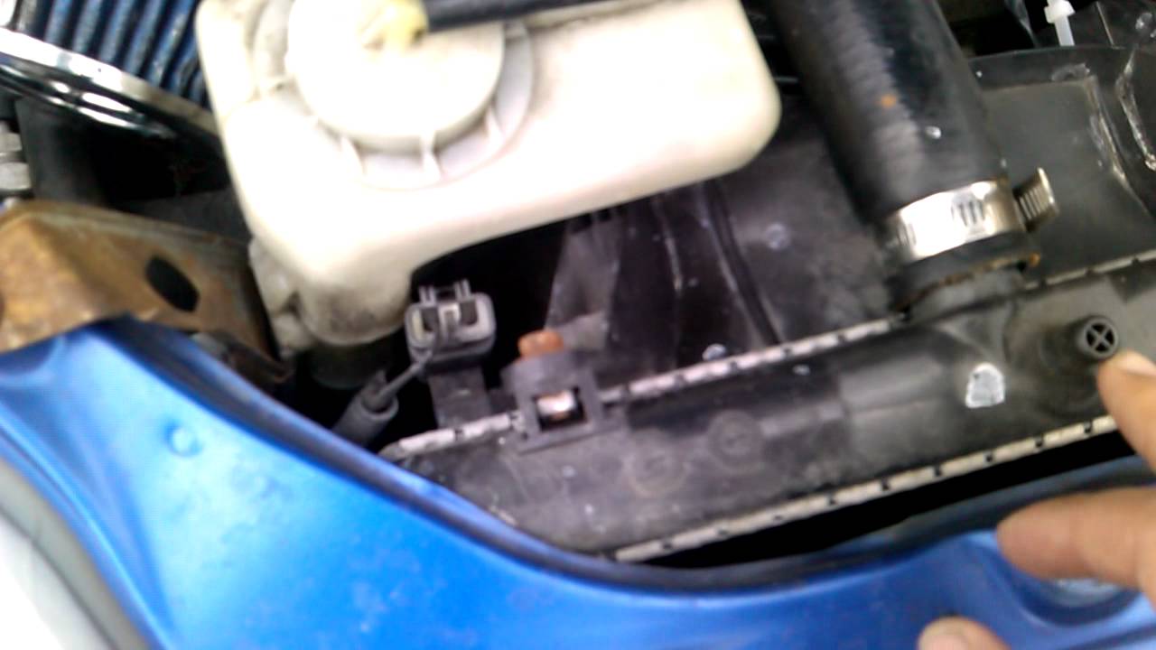
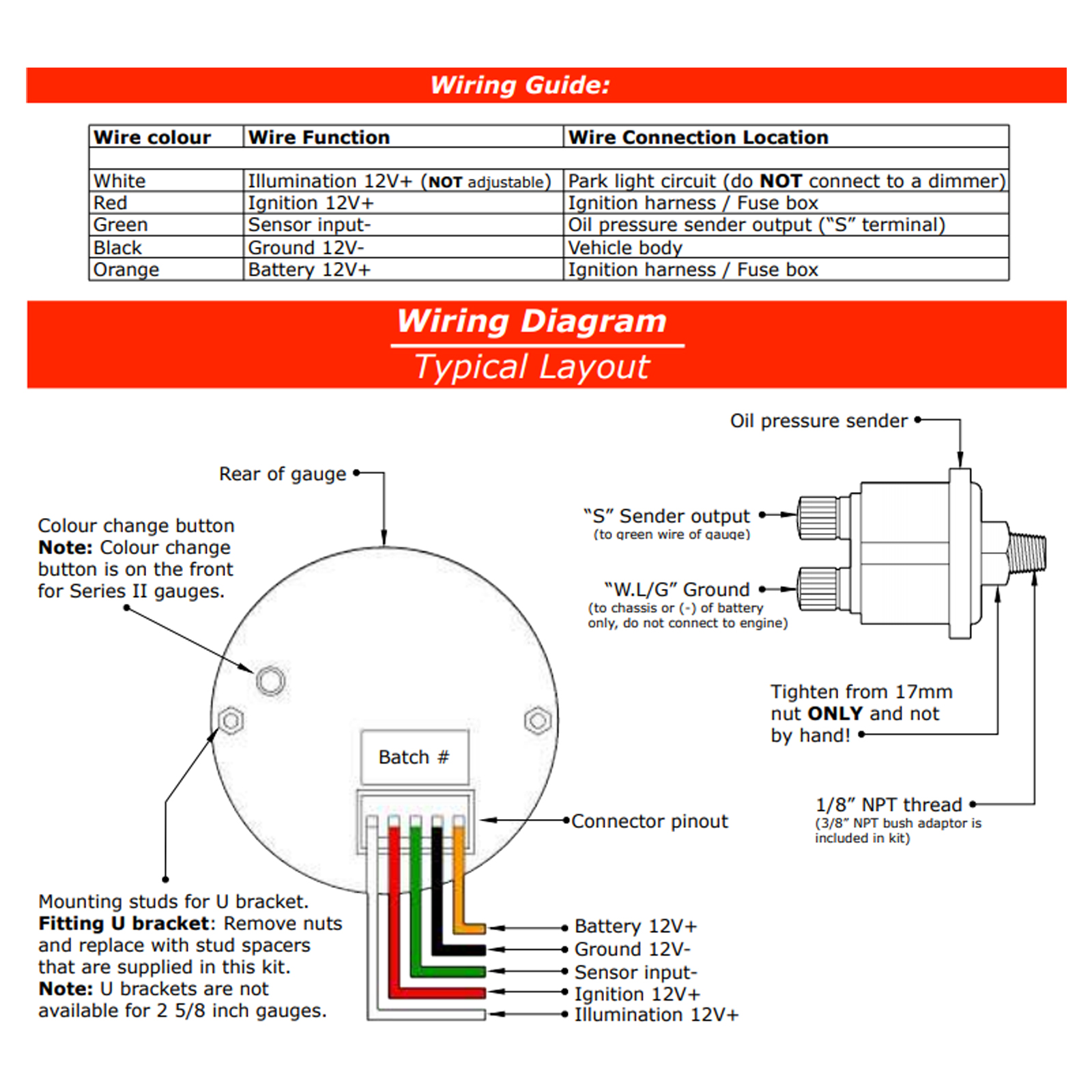
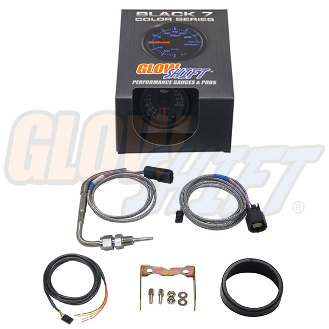
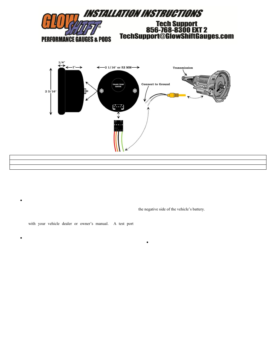
Glowshift egt gauge wiring diagram. Since our customers always come first your satisfaction is our top priority. This wiring kit features both sensor and power wires combined for each gauge. Boostvacuum gauge instructions wiring schematic disconnect negative battery terminal before starting any work on the vehicle. A wiring diagram is a streamlined standard pictorial representation of an electric circuit. At glowshift gauges we are dedicated to providing the best possible customer service available. Our glowshift support page delivers a multitude of helpful tools that are essential for our glowshift customers.
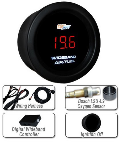
Boost gauge bar electronic boostvacuum gauge f exhaust gas temperature gaugeglowshift boost egt combo gauge user manual 3 pages new glowshift gauges wiring diagram glowshift 7 color series dual air intake temperature gauge user inside glowshift gauges wiring diagram glowshift digital series wideband air fuel ratio gauge user manual. This wiring kit is made with 20 gauge automotive grade wiring and features a length of 8 for the. For correct and proper glowshift gauge installation and operation the use of 18 gauge wire diameter automotive grade conductor wire with sheathing is recommended for one or more gauges per vehicle. 3in1 boost w digital egt pressure gauge. Glowshifts tinted series volt gauge will monitor your vehicles electrical system from 8 to 18 volts to ensure that it is operating properly and efficiently. High pressure oil pressure hpop gauge wiring harness.
Variety of glowshift boost gauge wiring diagram. Then connect the black wire of the. Add on clock power harness for 2002 2005 subaru impreza wrx. Whether you need to access glowshift install instructions. Glowshifts 7 color series 3 gauge wiring kit is a complete wiring harness that allows you to easily wire 3 tinted 7 black 7 or white 7 color gauges from one harness. Additional fused power wire for accessories such as gauges.
Connect the green wire from the gauge to the white wire of the transmission saved color your switched and untemperature sensor. Be sure to use a grommet when routing the line. And contact glowshift gauges. It shows the elements of the circuit as simplified forms as well as the power as well as signal links in between the devices. Glowshift gauges installation instructions and install guides. Route the boostvacuum line through the firewall from the engine bay keeping it clear of any moving parts heat sources and kinks.
Gallery of Glowshift Egt Gauge Wiring Diagram