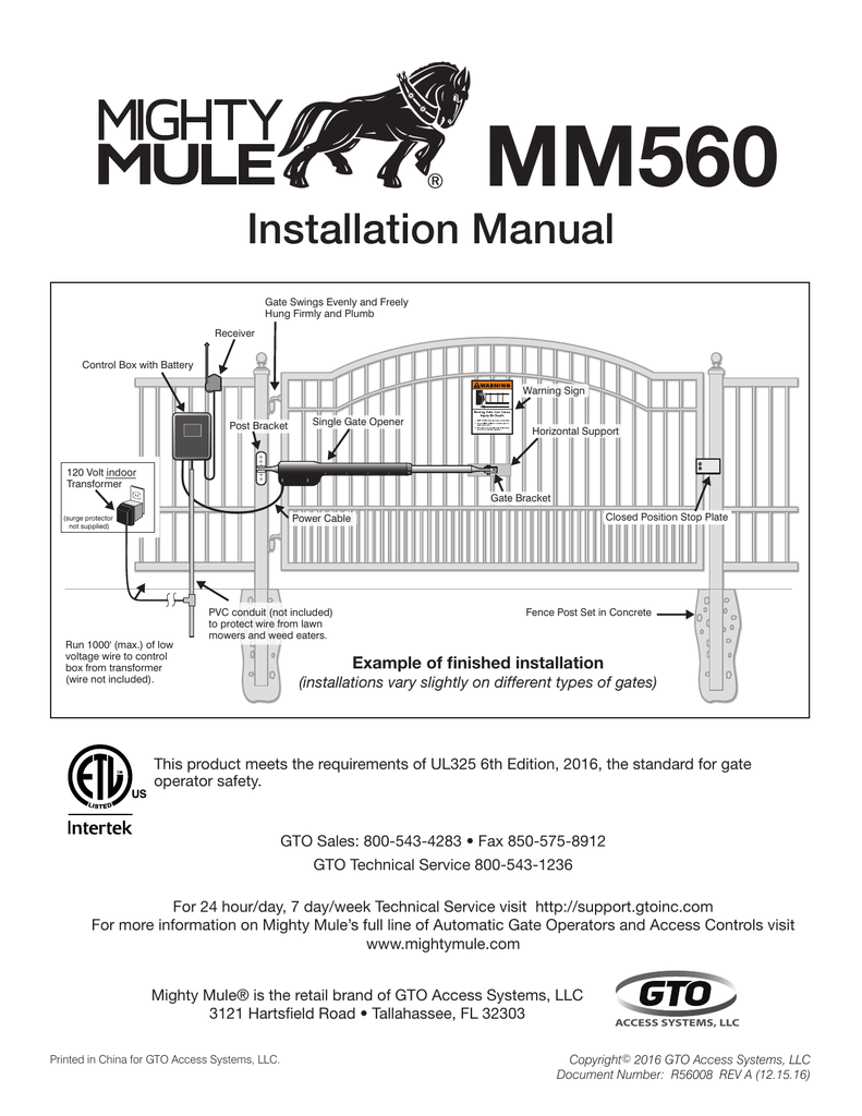
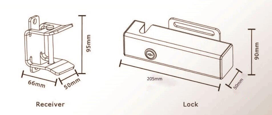
Remove hairpin clip clevis pin and bushing from either the front or rear mounting point. R4222 photo beams fm139 fm140 exit wand.

Death Spiral For Cars By 2030 You Probably Won T Own One
Gto exit wand wiring diagram. Connect the power input wires to power source. Connect the black to the terminal labeled common and the blue wire to terminal in step 3 to open gate. Fm145 bulldog pedestrian gate lock fm145 bulldog gate lock. Connect the black to the terminal labeled common and the blue wire to terminal in step 3 to open gate. The estate swing exit wand does come with a range control board that allow you to adjust the sensitivity of the magnetometer. This feature allows you tune down the range of the exit wand so that vehicles such as a lawn mower doesnt set open your gate but this.
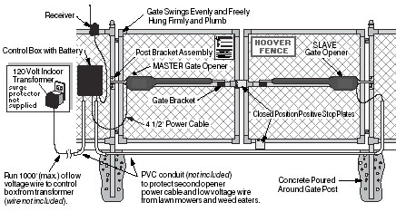
Battery connect the red wire to the. If you are using the exit wand low for wiring the system. Connect the power input wires to power source. Turn control box power switch off. Typical gate wiring connection. Connect the yellow and braided ground wires to the negative side of power source.
Connect the black to the terminal labeled common and the blue wire to terminal in step 3 to open gate. Gto exit wand instructions 122811 3 4. Connect the power input wires to power source. Because gto automatic gate openers are only part of the total gate operating system it is the responsibility of the consumer to ensure that the total system is safe for its intended use. R1300 magnetic gate lock r1300 magnetic gate lock. The gto exit wand is recommend for use with other gto openers and accessories.
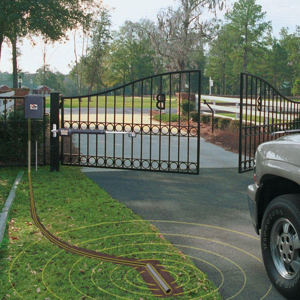
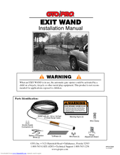
If you do not understand the instructions below please call gtos techni cal support at 1 800 543 1236. F310 g3 digital keypad r4500 wireless exit sensors f3100mbc estate intercomkeypad. Driveway exit wand photo beams fm144 automatic gate lock. Connect the yellow and braided ground wires to the negative side of power source. Disconnecting the opener 1. Gto wireless exit wand transmitter min max sensitivity.
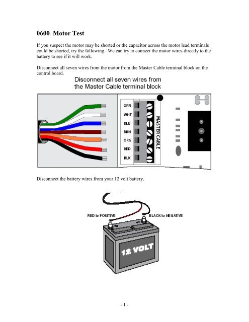
Gto exit wand instructions 122811 3 4. Battery connect the red wire to the positive side of power source. Gto exit wand instructions 091814 3 4. Wiring the estate swing deluxe exit wand to liftmaster la400la412 duration. Connect the yellow and braided ground wires to the negative side of power source. 4 fm130 sw instruction manual rev 050914 instructions for installing the decoder rcvr grn blk red rcvr r b g receiver grn blk red receiver terminal blocks blue green black red step 1.
Battery connect the red wire to the positive side of power. Turn the gate opener off. This video is about wiring es deluxe exit want to apollo. R4500 wireless vehicle sensor.
Gallery of Gto Exit Wand Wiring Diagram